I also modelled the box effects, and this has dropped the bass a fair bit once the baffle step comes in.
Just a hint:
It's very important to consider the baffle step in a crossover design. But in case of your woofer it's better not to model the box effects. Why? The frequency response of the driver is measured in a Seas test cabinet having almost the same baffle dimensions (310x210 mm) as your cabinet. Thus the measurement published by the manufacturer already includes the baffle step. Don't do it twice!
Thanks! I can get this woofer from Conrad Electronic UK. I'll have to make my own enclosures though, I've looked for the Dayton kits before and they do not seem to be distributed over here (UK). Shipping things over is usually very expensive, if you want to be sure they'll arrive.
Is the crossover diagram in the pdf file? I could see the image of the driver and the title text.
Please let me know how you get on with this one, thanks.
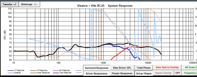
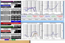
This is the PCD graph I have but it's the old baffle. I need to move the woofer forward a little and move it down, then re-valuate the crossover. It's not bad the way it is but the tweet is mounted on the edge of the top of the baffle. Plus, if I move the woof forward a little the phase tracking will be closer in time. Right now it's 21mm behind the tweet. With the new baffle it will be very close to zero Z axis. That will make the phase lines almost line up in the graph which should sound better as well. But, as with anything in reality it might change other things as well so I'll need to re measure and go over it again a few time, then assemble and listen and ...
THIS IS NOT INTENDED AS A FINISHED CROSSOVER
Woofer second order electric
1 mh coil
7.8 cap
Tweeter third order electric
12 mfd = 10 mfd + 2.2 mfd in parallel in series
.15 = .18 mh parallel to ground
90 mfd electrolytic or 80 mfd electrolytic plus 10 mfd plastic bypass to sweeten it up a bit. I would never put an electrolytic in series but in this case it's parallel and probably won't have any ill effect since it will be passing very little signal. Bypassing it with a good plastic will reduce or eliminate any harshness.
L-Pad
Series 7.5 Ohm resistor
Parallel 8.5 Ohm resistor
As you can see from the plot I have a ways to go to get the slopes the way I want them but phase is tracking over most of the usable range. The woofer phase crosses the tweeter about 200 Hz and track it till about 6K, but I can do better. I just didn't put the time into this version because I'm going to re cut the baffle. My version won't have any BSC and for sats you probably won't want any either. I'll get better measurements when I can set up over at the shop where we have a 40' ceiling.
Tom
Attachments
Last edited:
David Griesinger, top engineer at Lexicon, made the point in one of his papers that the lower in frequency you go, the more effective side or rear channels will be at creating a sense of envelopment. That suggests that the side or rear speakers should have a good lower mid and bass response. Personally I've found that side speakers up at the ceiling, half way between the listening position and the front speakers, aimed directly across at each other sounds real good to me. I found that full surround gets tedious to listen to after a while with music, so I don't bother with those.
Just a hint:
It's very important to consider the baffle step in a crossover design. But in case of your woofer it's better not to model the box effects. Why? The frequency response of the driver is measured in a Seas test cabinet having almost the same baffle dimensions (310x210 mm) as your cabinet. Thus the measurement published by the manufacturer already includes the baffle step. Don't do it twice!
Ah! It might not be such a bad result then. Thanks! I did look at the final model and wonder if the reinforcement from the wall behind would make a difference and decided 'not enough' but you're quite right of course, if there is already a baffle effect then the bass won't be so bad. The profile published does fall off from 1 kHz so that does make sense.
I'll load this up tonight at home and have another look. I really want to see if I could make a whole family of units from the same tweeter and woofer to give me a 5 speaker set up, if that is possible.
Thanks for taking my advice and not misunderstanding it as a put down. I get that often it seems. And I'm glad a major problem was solved before expensive parts were purchased.
I'm always happy to have my errors pointed out to me! Peer review is pretty much the main reason to post stuff like this on the web, and I really appreciate anyone taking time to read anything I've posted.
Also remember that using response modeler gives minimum phase. You'll need to enter the driver x, y, z coordinates if you're not measuring the drivers. For z, you'll just have to take a stab in the dark. I suggest -0.025 for the woofer and 0 for the tweeter. You won't be far enough off that it matters. You are, after all, using them as surrounds. So you'll likely rarely be on axis vertically.
Good luck")
Thanks again. I'm going to revisit this tonight and see what I can do with the phase minimised, but without the baffle step, taking into account Dissi's comments about the cabinet that the measurements were taken in.
As for the alignment, I was wondering about orienting the units with the tweeter and woofer in the horizontal plane, so the dispersion will be wide vertically, but narrower in the horizontal plane. The reason would be that they will be located higher than ear level, and I can rotate the speakers easily around the vertical axis to point at the listening position, and then I would not have to rotate them to point down.
David Griesinger, top engineer at Lexicon, made the point in one of his papers that the lower in frequency you go, the more effective side or rear channels will be at creating a sense of envelopment. That suggests that the side or rear speakers should have a good lower mid and bass response. Personally I've found that side speakers up at the ceiling, half way between the listening position and the front speakers, aimed directly across at each other sounds real good to me. I found that full surround gets tedious to listen to after a while with music, so I don't bother with those.
I found the paper http://www.davidgriesinger.com/objmeas.pdf, I take it that was the one? It's very interesting.
I feel like I have just finally entered the world of proper bass, after building a sub, and I'm currently working on the basis of buildling complementary speakers to work down to the sub. I'm currently experimenting with the crossover frequency, 80 Hz seems to work well with my current two way main speakers, although the 60 Hz frequency discussed in the paper as a target is perfectly possible to use, if I can design the rear speakers to work that low. Thanks for pointing this out to me!
I'll load this up tonight at home and have another look. I really want to see if I could make a whole family of units from the same tweeter and woofer to give me a 5 speaker set up, if that is possible.
That was the design goal with the Visaton / Vifa pair. At under $100 it's a decent deal. Make your own boxes and you can make them even cheaper. Did you say you already have drivers or were you working from factory data?
I like the finished Visaton HT, very revealing tweeter for it's size and that little woofer has very nice bass but I found a really good deal on the Aurum Cantus so I bought 6 of them. I'll be using the Vifa XT25TG30 for the AC-130's. The Aurum Cantus is much smoother and crossed down low will have excellent off axis response with that tweet. I bought mine on eBay and he probably won't ship out of country. He's in California. Holler if you decide to go this route and I'll post the final crossover. If you do decide to go the Visaton/Vifa route the boxes need to be .25 for .7 Q, I'm using a .23 and the roll off is so close it's nearly identical.
Tom
in surround arent the rears already high passed at the decoder? i always thought they were. Or are you using THX? i dont wish to criticise but if they are HP'd at the decoder, then your efforts may be wasted.
I have an Arcam AVR300 AV amp, which accepts a digital feed and does the decoding from DVD formats (it does not have support for the latest blu-ray formats, but the LG player I have can resample to 192 kHz Dolby DTS format). It can set the crossover between the sub and the rest of the system anywhere from 40-130 Hz so I'll be able to choose based on whatever works best for the system. I'm thinking of crossing at about 60-80 Hz based on keeping the front speakers smaller. If I can make the rear speakers so that they can play down to that range then that would be ideal.
With the AVR300 you can also choose to send the unfiltered signal to either the front, or all of the speakers if you want their crossovers to do the work, and you can also set it up to use the sub channel for HT but just use the front speakers for stereo signals, if you have full range main speakers. I can't help but think this feature is also for those whose subs play explosions better than music.
However, given that I have a miniDSP in the sub, I could just play full range to all the speakers and set the sub up to fill in below where the speakers roll off. This could give a gentler crossover slope than the one in the amp, which appears from measurements to be around fifth order.That was the design goal with the Visaton / Vifa pair. At under $100 it's a decent deal. Make your own boxes and you can make them even cheaper. Did you say you already have drivers or were you working from factory data?
I'm just playing with spreadsheets at the moment. I'm just beginning this!
I like the finished Visaton HT, very revealing tweeter for it's size and that little woofer has very nice bass but I found a really good deal on the Aurum Cantus so I bought 6 of them. I'll be using the Vifa XT25TG30 for the AC-130's. The Aurum Cantus is much smoother and crossed down low will have excellent off axis response with that tweet. I bought mine on eBay and he probably won't ship out of country. He's in California. Holler if you decide to go this route and I'll post the final crossover. If you do decide to go the Visaton/Vifa route the boxes need to be .25 for .7 Q, I'm using a .23 and the roll off is so close it's nearly identical.
Tom
So you have built a pair with the Visaton drivers? Can I ask what you use for measurement equipment and software? I think I'll need to invest in some testing equipment if I'm going to do this properly.
Just a hint:
It's very important to consider the baffle step in a crossover design. But in case of your woofer it's better not to model the box effects. Why? The frequency response of the driver is measured in a Seas test cabinet having almost the same baffle dimensions (310x210 mm) as your cabinet. Thus the measurement published by the manufacturer already includes the baffle step. Don't do it twice!
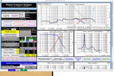
I've had another look, and if I use the Response Modeller to extract the phase, but do not add any box effects, on the basis that this data was taken for a 10 litre box, I can adjust the crossover and get this as the final response
An externally hosted image should be here but it was not working when we last tested it.
which seems +/-1 dB from 100 Hz to 10 kHz and then has a hump up to +2 dB to 20 kHz. At the bass end the response falls off from 100 Hz and is 3 dB down at just under 80 Hz.
Just to be clear, I've used the box model for a 7 litre box with the correct T/S parameters to generate the impedance curve, not the one from the specs, which is for a driver with no baffle. I take it this is the correct procedure?
The crossover for the woofer is third order electrically
L2 2.00 mH, 0.2 Ohms
C2 15.00 uF
L3 0.50 mH, 0.2 Ohms
With a parallel leg over the woofer containing C 20 uF and R 10 Ohms.
The tweeter has a third order section
C9 15 uF
L9 0.2 mH 0.2 Ohms
C10 25 uF
with a series resistor 2 Ohm after the crossover, and parallel resistor over the tweeter of 2.5 Ohms.
The null with the tweeter reversed is
An externally hosted image should be here but it was not working when we last tested it.
So, thanks again to Dissi for pointing out there were already baffle step effects in the Seas published response curve. I think this is now back to looking feasible for a rear channel design. The drivers would cost £66 each for the Seas U16RCY/P, and £23 each for the SB Acoustics SB26STC-C000-4, so this should be within budget if I don't get carried away on the crossover parts.
So, per speaker, for the woofer section
2 mH solid cored 0.18 Ohm about £5 (JANTZEN-5152)
15 uF cap, about £5 (Solen 15.00uF 400V DC Polypropylene Capacitor)
0.5 mH air solid cored 0.2 Ohm about £6 (JANTZEN-1267)
10 Ohm, 10 W ceramic £0.60
20 uF cap, about £6 (Solen 20.00uF 400V DC Polypropylene Capacitor)
and for the tweeter section
15 uF cap, about £5 (Solen 15.00uF 400V DC Polypropylene Capacitor)
0.2 mH 0.2 Ohms, air cored £1 (JANTZEN-2078)
25 uF cap, about £7 (Solen 20.00uF 400V DC Polypropylene Capacitor)
2 Ohm and 2.5 Ohm resistors, 10W ceramic £0.60 each
for a total of £36.80. Bugger, that's more than I was expecting.
Allowing £10 for materials for each cabinet (mainly the cost of epoxy glue) this gives £135.80 per speaker. Not too far over budget, but if someone was to get excited about fancy caps you could almost double it, they are all quite large. I would be interested if anyone has suggestions for decent but cheap capacitors other than the Solens, or if anyone can confirm if they should be fine.
Some decoders probably do cut the bass, citing that most side or rear channel speakers are going to be small (wife acceptance factor) and not able to go very low in freq. Most bass is mixed in mono too. It wasn't until I read many of the David Griesinger papers that I realized that you really do want stereo bass, and as much bass as is practical on the side and rear speakers. Griesinger is one of the best in the world. All his papers are worth the time to read.in surround arent the rears already high passed at the decoder? i always thought they were. Or are you using THX? i dont wish to criticise but if they are HP'd at the decoder, then your efforts may be wasted.
I'm just playing with spreadsheets at the moment. I'm just beginning this!
I've been fiddling with speakers for years, even decades but only recently got equipment to take measurements so I'm pretty new too. What you did so far looks great, but factory data is probably not going to work on the actual driver. Many woofers have their T/S parameters measured at 2.83 volts which violates the entire premise of "small signal parameters". Recently I purchased a TC Sounds EPIC that measures fs 31Hz but it's advertised at 24 Hz. It's impedance slope is different than what I measured as well. When I run the voltage up I get 25Hz fs and .40 Qts which is close to advertised, and that was with few hours on it. The Visaton in this project measure higher fs than spec even after break-in but again, run the voltage up to 1.5 or so and it measured correctly. What they tell me is that it more accurately represents the driver "in-use", which may or may not be correct. It does make sense on a large woofer like the EPIC where the surround is thick but not on that little 5".
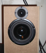
Yes, I've got them in my kitchen. Waiting for some parts to arrive so I can go cut new baffles. Probably tomorrow. I cut the tweeter hole too high on the baffle. It reduces baffle diffraction effects but messes up vertical axial response. See image below.So you have built a pair with the Visaton drivers?
I first bought a Dayton Audio calibrated mic and registered a copy of ARTA/LIMP/STEPS. I bought a sound card with phantom power for the mic but I don't know the amp gain. I recently measured it at full output and it's quite low (30) but at least I can take accurate SPL measurements. LIMP is good for impedance curves and to test inductors/resistors/capacitors but you need to make a "jig" or get some 1% resistors for reference. I bought a jig off here. It was a project someone made then he left and we haven't heard from him since. It has a reference 10 ohm resistance on a push button switch and a built-in TDA2030 single chip amp so I don't have to have a big nasty amplifier sitting on my desk. It has separate probes for amp and impedance measurements. I also use it to take impedance measurements but I had to make an external impedance probe. I also use it for listening tests, it's a clean little amp putting out about 4 watts with the power supply I have (1 Amp 24V)Can I ask what you use for measurement equipment and software?
I also have an Omnimic. It's a USB based mic and software for acoustic testing which is nice because it run on a laptop. It comes with a calibrated mic and very good software and you can use the mic in ARTA. I haven't figured out the preamp gain yet. It has a preamp that is part of the mic and they don't publish the data. They do publish the mic sensitivity though but I'm not genius enough to figure it out.
I'd invest only if you're going to be using it to do more than a single speaker system. There are several places here within 10 miles of me that will do acoustic testing for me. I'm thinking of advertising to take measurements for people if I can find a good place to do it. I would either need to make a closet sized anechoic chamber or get some really tall speaker stands. Anechoic chamber sounds easier than a 15' tall stand for both speaker and mic.I think I'll need to invest in some testing equipment if I'm going to do this properly.
Easiest thing there is for acoustic testing is Omnimic. But you can purchase a Behringer calibrated mic for under $100 online and either make or purchase a calibrated preamp. If you go the cal mic route make sure you either know the preamp gain or that it has calibrated gain settings. Then you can use ARTA/HOLM Impulse/ Speaker Workshop or one of the other free or mostly free programs for taking measurements with a sound card. I've found that most sounds cards are decent enough for good measurements. Mine has a low noise floor (over 60 db) and only has slight roll off at 5 and 18.5K. If you want really accurate measurements you can make a .cal file for ARTA that includes the sound card FR and phase compensation. Mine would only need a few samples for calibration, 3 or 4 on the bottom to account for the roll off below 10 hz and maybe 10 or so points to account for the HF roll off on the top end. You'd have to manually combine the sound card calibration with the mic calibration to get it correct but that's easy in Excel or Openoffice Calc. ...Anyway...
For impedance you can use the unregistered copy of LIMP, a sound card and a 1% reference resistor. No need for calibration. It uses the "constant voltage" method of measurement that requires no calibration except the reference resistor. It uses the sound card output (up to 2 volts) to measure T/S parameters but on some drivers you need an amp and external resistor to get the necessary voltage. All you really need is to know the exact resistance of your reference resistor to get accurate results. I forgot to add that the sound card probably doesn't give as accurate results because the impedance back to the sound card it so high whereas the impedance of the amp is quite low, below 100 ohms for sure. Point is if you're going to take impedance measurements you'll need a at least a small 5 watt or large amp.
Well, this is getting way too long. Hope I've helped.
Attachments
Last edited:
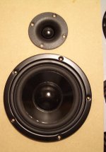
I got the parts today and cut the new baffle. Got the second woofer breaking in and the flat-pack boxes I need to finish the project. I have the other tweet and some more crossover components coming in a day or two but I think I have enough parts to flesh out the final crossover. At least I can get the values I need and do a listening test with two speakers. I might need to adjust things depending on the DC resistance of the inductors.
It should be easier to get off axis response to be more even now. I'm still deciding if I will flush mount or not. I don't think it's going to make that much difference on this speaker plus with the drivers surface mounted like the picture the Z axis is nearly zero. This woofer has recessed screws and a rolled edge so it's edge is very smooth. It's only 1/4" high too. The tweeter lip is only 1/16th" so it will have very little diffraction effect. Don't know if it's worth the trouble.
Opinions?
Attachments
Last edited:
I would be interested if anyone has suggestions for decent but cheap capacitors other than the Solens, or if anyone can confirm if they should be fine.
There are some good articles on how different components act in terms of insertion loss and how they effect overall sound. Insertion loss is only part of the issue though. Generally speaking inductors cause the biggest issues as they are, in fact, simply coils of wire. But the wire size (12 vs 18 gauge), type (OFC or not), shape (square, triangle, flat), coil shape (round, toroidal, tubular) and DC resistance all have an effect on the final inductor. IMHO, the inductor is by far the most important component in a passive crossover. Caps induce very little resistance or insertion loss. Neither do resistors. Inductors, on the other hand, can make or break a crossover. Most digital crossover designers make some basic assumptions about inductors and in general assume they are purely inductive. I'm looking for the article I read a while ago that really opened my eyes to inductors and their contributions to a finished speaker system. I'll post the link when I find it.
But you were asking about caps. I think much of the hype about caps is just that, hype. While there is a difference between an electrolytic and a plastic cap and while we used to use Mylar caps and don't much anymore, I don't see the real value in paying $45 or so for an "Audiophile" capacitor. I doubt you'd hear the difference in most cases unless you're in a very quiet room and are under 30 in age. I shop at Parts Express, Madisound or Radio Shack myself.
I got the parts today and cut the new baffle. Got the second woofer breaking in and the flat-pack boxes I need to finish the project. I have the other tweet and some more crossover components coming in a day or two but I think I have enough parts to flesh out the final crossover. At least I can get the values I need and do a listening test with two speakers. I might need to adjust things depending on the DC resistance of the inductors.
It should be easier to get off axis response to be more even now. I'm still deciding if I will flush mount or not. I don't think it's going to make that much difference on this speaker plus with the drivers surface mounted like the picture the Z axis is nearly zero. This woofer has recessed screws and a rolled edge so it's edge is very smooth. It's only 1/4" high too. The tweeter lip is only 1/16th" so it will have very little diffraction effect. Don't know if it's worth the trouble.
Opinions?
So this is the Vifa BC25SC06 and the Visaton W130S! I like the fact that the tweeter is sat back more, and should be closer to the woofer centre. As to the mounting, I had a pair or JBL LX33's back in 1989 (my dad still has them, they've not gone far) which had rolled metal edges to the drivers like those, and they were not recessed, but there was a thin (3 mm or 1/8") layer of grey foam rubber round the driver that the edges compressed into to form an airtight seal. Might be do-able for these? If you got a square of it you could fit it up the tweeter too and then that would fit almost flush to the foam, plus I believe the foam is better than meeting an edge with regard to diffraction of the treble? Image from (http://www.hifidatabase.com/)
An externally hosted image should be here but it was not working when we last tested it.
Are these going to be redeployed now that you are working on the Aurums?
Cheers,
Nick.
The woofer was about 21mm behind the tweeter when measured using PCD and Jeff B's Z axis process. It will be at least 1/2" closer to zero now which is around 12 mm. Phase should track closer together over the entire range and be easier to line up with a 2nd on woof and LR4 on tweet but sometimes it's difficult to get phase to track if they are too close to zero. I'll have to fiddle with slopes but the goal is to prevent the woofer phase from crossing the tweeter phase at all. I know there is some math behind figuring this out but it's beyond me at the moment. I won't know until I take measurements and start to model it. Probably tomorrow afternoon if I can find a place to run the router for a few minutes. I live in an apartment and wouldn't even think of running that thing in my house. But there are storage lockers downstairs about 10'x10' that would be acceptable. I might just go out on my porch tomorrow and finish the routing I need to do so I can spray the panels with Quiet Kote to deaden the panels then glue up the cabinets.So this is the Vifa BC25SC06 and the Visaton W130S! I like the fact that the tweeter is sat back more, and should be closer to the woofer centre.
I was originally going to make 5 of them but put that idea on hold when I found the other woofers. I don't know what I'll do yet. I might sell them to a friend who's never owned an audiophile speaker, give them to my son as a gift (if he promises not to torture them with his digital amp) or sell them on Craigslist after I paint or cover them in veneer.Are these going to be redeployed now that you are working on the Aurums?
Nick.
I'm thinking ahead but only working on one project at a time. I have to finish these first or I'll get all messed up. I have a test enclosure for the Aurum Cantus but I haven't cut the baffle yet. I'm probably going to try the Vifa XT25SC90 (small 40 watt neo version of the larger 90 watt Vifa and ScanSpeak Discovery R2604/8320 1" Tweeter Ring Radiator) with it first. It won't cross down at 1.5K with that little neo tweet though. The XT25SC90 has an fs around 700Hz but the Scanspeak has an fs around 450 Hz so it should cross down low much easier. However, just because they got the fs lower doesn't mean it will handle more power. It's still rated about the same but Scanspeak has modified the resonant cabinet for a lower fs which means lower distortion. I've been told there are better tweeters to use so I haven't decided yet. Could use the Dayton Audio Silkie or its aluminum cousin or even the ScanSpeak Discovery D2608/9130 1" Textile Dome HDS Tweeter which is said to be a better sounding tweeter but it's $80...
I modeled the new position using the old sweeps and it looks better already. Phase tracks much closer over the spectrum. This will be a decent little speaker.
Tom
Attachments
Last edited:
I usually put a bead of silicone around the edge to make a gasket and to help seal but now I have 1/8" foam tape just like what you describe. Parts Express also has foam and other acoustic panels you can purchase for not too much. I'm also going to spray the interior of these enclosures with acoustic damping spray. An alternative is to use a panel of damping foam. I'll also place a little bit of acoustic stuffing in each box. I don't tack it to the sides, I just place it loosely in tbe enclosure behind the woofer. It's only there to break up the mid range back wave from the woofer, not to alter the enclosure effects. It should reduce any mid range nasal effects from standing waves.I had a pair or JBL LX33's back in 1989 (my dad still has them, they've not gone far) which had rolled metal edges to the drivers like those, and they were not recessed, but there was a thin (3 mm or 1/8") layer of grey foam rubber round the driver that the edges compressed into to form an airtight seal. Might be do-able for these? If you got a square of it you could fit it up the tweeter too and then that would fit almost flush to the foam, plus I believe the foam is better than meeting an edge with regard to diffraction of the treble?
Nick.
That's a diffraction panel to reduce baffle diffraction effects. It may reduce diffraction but it also reduces efficiency to some extent. I think I'm going to try it without flush mounting. As long as I don't see peaks and dips in the response curve it will be fine. I could also model it in Jeff B's diffraction simulator. I don't know if it will model diffraction effects on the surface of the baffle though. It's easy enough to run the router over the opening after the box is glued up so it's not a huge deal. Are you thinking of this pair up as a possibility? Can you get these drivers at decent prices?
Last edited:
DrNick - RE Post 31.
That looks great. Nice cross over point. Good driver integration. Very flat response. Relatively simple cross over. Just to be clear though, you did enter driver offsets? Woofer z should be something like -0.025 if using the newer version of PCD. The older version should be 25.0 or something iirc.
This shouldn't make a terrible difference, it's probably fine.
DrNick - RE Post 31.
That looks great. Nice cross over point. Good driver integration. Very flat response. Relatively simple cross over. Just to be clear though, you did enter driver offsets? Woofer z should be something like -0.025 if using the newer version of PCD. The older version should be 25.0 or something iirc.
This shouldn't make a terrible difference, it's probably fine.
Yes I did. My earlier Z axis measurement was wrong. The mic moved between measurements when calculating Z axis so the phase was off a little (measured with mic on carpet). The correct Z offset was -.022. The old z offset was -.022 and the new offset I guessed at -.012 but was wrong too, it should be -.01565 (22 - 6.35 [1/4"] = 15.65 mm) based on moving the woofer 1/4" forward.
I changed the offset and used the existing measurements. It won't be exactly correct because the new woofer measurement will be more off axis than the original but it's not by very much. I measured both drivers on tweeter axis and used the phase data from Omnimic directly. When I get the crossover installed I'll reverse the tweet and double check the dip. If it matches both depth and frequency I'll know I have valid phase data and subsequent phase tracking. If not I'll try again. I want to go back and use ARTA and try out the "minimum phase" measurement. When you take the measurement with ARTA you select the same number of samples (gate time) for each driver making sure to get the correct point on the impulse response where the signal just begins. Then you select a frequency response display and make sure phase is displayed. Then select "minimum phase" and the phase displays as a wavy line. If I am correct the "minimum phase" conversion begins with zero phase and includes only the phase delta rather than absolute phase. It should be easier to use since there would be less 180 crossings but I'm not sure if my surmise about minimum phase is correct. Can't seem to find that specific information.
This next set of measurements are going to be taken outside on my porch. I live in a second story apartment with laundry below me. The porch is 15' off the ground. If I set the speaker on the edge of the railing and the mic 1 meter away, on the porch, I should be able to gate down to 90 Hz, maybe even lower. Assuming the first reflection is the floor of the porch or the building behind the mic the floor is the closest object about 8' away. There would be nothing behind the speaker for over 100' and nothing below for 20', only the porch in front and the 2" railing its sitting on. It will definitely be better than indoors as long as I average till it's stable. 5-7 is usually enough averaging but I'll have to see. Over averaging makes the FR slowly drop downwards. Not sure why yet.
As for flush mounting the woofer I probably won't. I already cut the hole and the woofer has a rather large 3/4" lip. I'd have to either buy an expensive 1 3/4" rabbet bit and remove the bearing or plug the hole with a scrap, clamp it all down and use a straight bit and the circle cutter. If I don't get it perfectly centered it will be out-of-round and look horrible. The time to rabbet the opening is before I cut the hole. I do it this way: First I set router buddy to a 5 3/4" circle, straight bit depth to 1/4" and make the rabbet, then set the circle for 4 1/4" and cut progressively deeper till I'm almost through. The last 1/32" I leave attached, punch out the plug and use a straight panel trim or chamfering bit to finish the edge. I do need to chamfer the inside and round-over the front baffle before I glue it on though. I'm looking at a reconditioned Ryobi router table with vacuum port and all the fences/guides/external wiring for $79, including a year warranty. I can't pass it up but I don't have a place to put it... yet.
- Status
- This old topic is closed. If you want to reopen this topic, contact a moderator using the "Report Post" button.
- Home
- Loudspeakers
- Multi-Way
- Design for a cheap two way for use as rear speakers in 5.1 setup