That looks pretty close, at first glance. I don't know hornresp well enough to help you.
Of course the best idea is to built it and measure it. Then you will really know what's going on. You could have your active crossover ready to go and just plug in the values you need.
Better yet (IMO) build the passive version to hear if you like it. You may, or may not, want to alter the filter functions of the passive version.
Okay, I now have acquired the drivers, the wood cuts (in 22mm MDF) and most of the other things I need for the speakers. The drivers are currently breaking in, and will get plenty of hours before being put into the cabinets. I'll also be trying my luck with a router to add chamfered edges to the front baffle and flush mount the drivers.
And I will also get the parts for the (external) passive XO and take my time going active. I'll "design" a 3rd order spread frequency electronic crossover, with an added shelving lowpass for baffle step correction (3dB around 500Hz) in the woofer section, and an allpass in the tweeter section (the latter for time/phase alignment).
I'll keep you posted on my progress, maybe there's something of interest to others to be seen here.
Before I go ahead, can someone check my crossover design please?
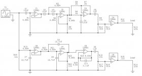
Like I said, I'm going with the 3rd order Butterworth electronic crossover, low pass at 2.5kHz, high pass at 3.5kHz. I added a 3db baffle step compensation for the woofer at 526Hz (baffle width of 231mm), a 60us time delay for the tweeter, and output buffers with individual level setting potentiometers (Bourns 3386). A DCB1 will act as the input buffer to drive the 1st order low/high pass from a low impedance source.
About the all pass for time alignment of the tweeter: When the drivers are mounted, the woofer's voice coil is approximately 45mm behind the tweeter's, which would translate to about 130us delay. Since the high and low pass are 90° out of phase, then with the right polarity the tweeter will be lambda(3.5kHz)/4=24.5mm~71us behind, which leaves just around 60us for the all pass. Correct?
Do the resistor values look okay in general?
Would you change the level setting and output buffer circuitry? Maybe to a variable gain stage? Or would using the output buffer to drive a lower impedance pot (moving the pot from buffer input to buffer output) result in lower noise?
Attachments
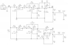
Here's a revised version of the crossover.
I made a mistake in calculating the baffle step frequency in my initial design. I made some corrections and calculated the new resistor values according to Baffle Step II.
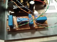
I'd like to ditch the conventional DC coupled level controls and directly drive a 2k linear potentiometer in series with a 3k resistor with the last stage of the filter. The woofer amp is DC coupled at the input and there will be a large cap (>20uF) in series with the tweeter, so I don't think there is any need for additional DC blocking caps.
Would anything advise against building the circuit on a double sided prototype board (Roth RE321-LF) with a copper ground plane on top?
I made a mistake in calculating the baffle step frequency in my initial design. I made some corrections and calculated the new resistor values according to Baffle Step II.
I'd like to ditch the conventional DC coupled level controls and directly drive a 2k linear potentiometer in series with a 3k resistor with the last stage of the filter. The woofer amp is DC coupled at the input and there will be a large cap (>20uF) in series with the tweeter, so I don't think there is any need for additional DC blocking caps.
Would anything advise against building the circuit on a double sided prototype board (Roth RE321-LF) with a copper ground plane on top?
Attachments
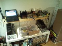
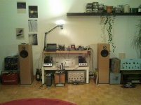
I managed to finish the speakers last weekend, and they are already hooked up to my "new" system.
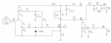
For now I settled for a 2nd order PLLXO that is being driven by my trusty old BOZ. Since the BOZ has a 5k lin pots at the output, I connected the insertion loss-ridden LP on top of the pot, and the HP via the wiper. This gives a nice level control for high and low frequencies. Global volume is managed via a 25k log pot at the pre's input (R107 100k resistor to ground removed). I've added a schematic. I could also start a new thread on the BOZ PLLXO if someone is interested and go into detail there.
The LP@2400Hz is then fed into a LM4780 stereo amp which has an input impedance of 15k, so with the 10n and 1n caps I had on hands I was left with 6k6 and 66k resistors for the passive XO.
The HP@3500Hz is fed into my lovely Mini Aleph which has an input impedance of approximately 23k1. This input resistance is being used as the second resistor of the passive XO, so with 10n and 2n cap I only needed an additional 5k7 resistor to complete the filter. For details and a nice spreadsheet see TLS.org | Passive Line-Level Crossover
I'm now tinkering with the HP/LP level matching. Any hints on that? I was using pink noise and the real time audio analyzer app of my smartphone to get an idea, and will not see how it matches with what I hear.
The bi-amped system sounds incredibly good so far, crystal clear, fast and punchy. Totally worth the time and effort methinks.
I wonder how big an improvement 3rd order slopes (active), baffle step compensation and proper time alignment could bring additionally...
Attachments
Hm, something just occurred to me: Couldn't I just add a 1st order crossover at the speakers to approximate a 3rd order filter function in total? An inductance (~0.4mH) in series with the woofer, and a smaller cap (~7.5uF, currently 23uF) in series with the tweeter for example. Combined with the 2nd order PLLXO it should have a character closer to 3rd order, no?
- Status
- This old topic is closed. If you want to reopen this topic, contact a moderator using the "Report Post" button.
- Home
- Loudspeakers
- Multi-Way
- Questions regarding electronic crossovers, bi-amping and impedance equalization