GM I built a test cabinet.........
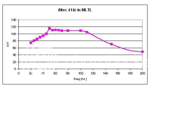
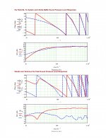
OK, so driver and vent location is off by a minor amount due to increased height, smaller CSA/net Vb, ergo tuning with the specified vent tunes it a little higher as shown in a sim.
Note that the driver’s Sd/eff. dia. per Altec is 507.529 cm^2/254.2 cm, so simmed SPL is a little high.
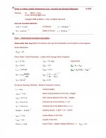
To get BL, I calculated it and found a minor discrepancy between Mms, Cms, Vas, so changed Vas to match: 229.597 L.
Le is an average of several measured ones.
Again, to make sure we’re on the same ‘page’:
GM
Attachments
![Altec 414Z MLTL - test [vinylnvalves].gif](/community/data/attachments/332/332554-5d52fbdba20bb4cde1b98804d6a14f38.jpg)
My experience with expanding MLTL designs.....
FWIW, MJK's documented expanding taper ML_TQWT is 60" i.d. and also my default height for a constant [straight] taper MLTL, which I empirically arrived at long before his was published. Not sure what this has to do with VIV's MLTL though.
Yes, I considered room modes, but with driver Fs at ~35 Hz and tuning around Fs, there would normally still be an obvious null in the driver's response and a peak in the vent's when measured separately, yet it's the opposite, so for now I'm sticking with an air leak.
GM
Wasn't sure what VnV had actually, read as expanding taper
Have read through Martin's work, super job and wish this was around 20+ years ago. Haven't used his worksheets tho for various reasons, all of which I'd like to resolve... am using Leonard Audio Transmission Line, latest beta. Have run sims using this and compensate for it's anomalies based on same drivers simmed with the worksheets. Sure beats antenna design applied to acoustics which is how I use to do it on a TI59/hp41c. Alot of trial and error back then
61" length does ring a bell with one I'll probably build, give an inch or so. Negative taper to keep length down. Todo the same with a straight taper would require a length of 95-100". If it was one driver I'd fold up, but this is 3x = far too much box for my likes. Also what influenced my comment.
We are on same page as far as inputs into MJK's worksheet is concerned. I see that the favourite culprit is leakage.
From a cabinet leakage perspective the only holes are the vent and where the driver mounts. The altec driver as you well know has a vented dust cap, and from what i can see is the only source of leakage, assuming the surrounds aren't porous, which they don't seem to be. Do i need to include the dust cap leakage in my simulations, and if so how.
From a cabinet leakage perspective the only holes are the vent and where the driver mounts. The altec driver as you well know has a vented dust cap, and from what i can see is the only source of leakage, assuming the surrounds aren't porous, which they don't seem to be. Do i need to include the dust cap leakage in my simulations, and if so how.
Not unless somebody drilled a hole in the back of the motor or similar. The surrounds are cloth covered with a goop than can become porous over time, but it's a rarity except on some non-Altec approved re-coners that have been known to leave it off entirely!
Seemingly well constructed cabs can/do leak, ditto 't'-nuts or similar and since MLTL cabs generate more acoustical pressure than a typical reflex, they tend to leak more, even between the threads of the mounting hardware screwed into them.
Under/over-tightening the drivers to the baffle can cause leaks too. Among others, Altec designed/tuned under the assumption of a certain amount of leaking and why they sometimes measure way different to what they sim.
I'm not going to stand on a stack of bibles and swear it's an air leak, but until proven otherwise I'm going with what it almost always is no matter what the alignment and/or driver used.
Of course, not being there I assume the measurements reflect reality, which considering their seeming oddity I'm not convinced they are.
GM
Will check the leakage paths and seal where appropiate and remeasure. Interestly had an experienced audiophile arround this evening - and he commented on how naturally sounding and extended the bass was - and how much he looks forward to hearing the system when the LF is not mono. He has "golden ears" so maybe i need to check the measurements again.
Well, that's how a MLTL should sound, so now I'm shifting towards a measurement issue.......
Then again, if there's significant room gain and the cab is high tuned/lossy, i.e. semi-aperiodic, then it could perform very well also.
An impedance measurement should 'tell the tale'.
GM
Then again, if there's significant room gain and the cab is high tuned/lossy, i.e. semi-aperiodic, then it could perform very well also.
An impedance measurement should 'tell the tale'.
GM
Checked around the cabinet no leakage paths as far as i can see - caulked the lid down to make sure - no change in the FR traces.
Carried out a electrical measurement of the driver in the cabinet. Sorry for the crude approach only had a signal generator and a multimeter to hand. It does not give the trace i was expecting - no twin peaks either side of Fs - so not working as a BR as far as i can see.
Not sure where or what to do next ?
I am unclear if its the driver not being as measured or something else. I have some Supravox 285gmf's i could try in the cabinet to see if the sim for their parameters.
Carried out a electrical measurement of the driver in the cabinet. Sorry for the crude approach only had a signal generator and a multimeter to hand. It does not give the trace i was expecting - no twin peaks either side of Fs - so not working as a BR as far as i can see.

Not sure where or what to do next ?
I am unclear if its the driver not being as measured or something else. I have some Supravox 285gmf's i could try in the cabinet to see if the sim for their parameters.

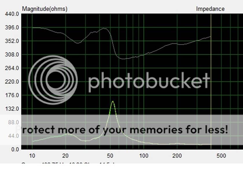
Checked around the port - pushed the stuffing away from the opening, no real affect. Attached 2 more traces, the first with the free driver impedance overlayed. In the second one i started the measurement from 10hz, this highlights the second peak maybe around 20hz?
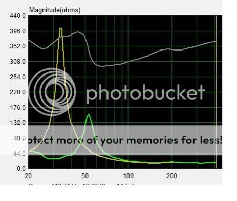
Just in case you are confused the second trace is phase.


Just in case you are confused the second trace is phase.
In playing with the MJK sheets, I could often get a response like this using a really large high aspect ratio vent. I have not seen the official drawing of your schematic. What are the complete details of the enclosure? Ts parameters of your driver. Also seems to happen when the taper of the enclosure is tapering heavily towards output/port.
OK, now I'm seeing what I expect to see except that it's damped enough to shift tuning down more than expected with a below Fs tuning, so you may want to experiment with less internal damping, which will make it not quite so 'dry' sounding.
For sure, no air leaks unless the damping material is covering them up real well.
GM
For sure, no air leaks unless the damping material is covering them up real well.
GM
IT looks very similar to impedance plot of box for aLtec 416 based on similar box sixe folded over. If I lengthen vent, it pushes first hump lower in frequency and raises second. As you reverse this activity, the humps begin to equalize out. As GM stated, stuffing is another way to dampen the first impednace hump.
Attachments
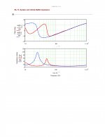
Measurements made using soundcard.
The cabinet is made as you described with a central baffle to make the fold. 63" long straight line 11" deep ~18.3" wide with the driver and post as instructed. The only thing which has crossed my mind is that to allow me to fine tune the port i router a slot ~ 8" wide x 12" long with curved ends onto which i attached a plate with the port in it, on the outside of the cabinet - could it be acting like a 2 stage chamber. Will attach plate on the inside of cabinet tommorrow evening and remeasure if its felt that this could be the culprit.
The cabinet is made as you described with a central baffle to make the fold. 63" long straight line 11" deep ~18.3" wide with the driver and post as instructed. The only thing which has crossed my mind is that to allow me to fine tune the port i router a slot ~ 8" wide x 12" long with curved ends onto which i attached a plate with the port in it, on the outside of the cabinet - could it be acting like a 2 stage chamber. Will attach plate on the inside of cabinet tommorrow evening and remeasure if its felt that this could be the culprit.
- Status
- This old topic is closed. If you want to reopen this topic, contact a moderator using the "Report Post" button.
- Home
- Loudspeakers
- Multi-Way
- Cabinet Design for Altec 414z's