At the November 2012 Central Kentucky DIY Speaker event I heard Bryan Keane’s Triton MTM bookshelf speakers. Bryan used Jeff Bagby’s prototype Triton design for Creative Sound Solutions (CSS) as the model for his speakers. I was impressed with the imaging and clarity of Bryan’s speakers and they were easily the best bookshelf speakers at the Central Kentucky event. Jeff’s design is superb and well executed as explained in the white paper on this design at:
http://meniscusaudio.com/images/Triton Kit Write up.pdf
Bryan Keane’s Triton MTM build thread is:
Jeff B's CSS Triton High Resolution Monitor
Robert Woods has a similar build thread at:
http://www.diyaudio.com/forums/mult...esolution-triton-kit-designed-jeff-bagby.html
The drivers are interesting in their size (small) yet low distortion realization. Both have patented XBL2 technology which was developed by Dr. Dan Wiggins during his tenure leading Adire Audio. Dan invented a driver design that extends the linear travel of the moving parts of the speaker so that measured distortion levels are reduced compared to standard technology.
Under the sponsorship of Creative Sound Solutions (a Canadian DIY loudspeaker parts distributor), the new XBL drivers are the CSS VWR126X mid-woofer and the LD25X tweeter. The very wide range VWR126X is a 4.5" diameter unit. Along with the XBL motor system, this driver features a woven Polypropylene cone, rubber edge, cast aluminum frame and copper dust cap. The likely driver application of the VWR126X is as a premium mid-range in multi-way systems. The LD25X tweeter features a small flange and the XBL motor system—the first for a tweeter—and is perfect for MTM and other limited baffle space designs. The distortion levels are some of the lowest measured. Both of these drivers were introduced to the market for DIYers early in 2012 and you can check several threads on DIYAudio and Parts Express Tech Talk forums threads on the Triton MTM bookshelf design.
My MTM design with the CSS drivers is realized as a mass loaded transmission line (MLTL). The MLTL configuration extracts optimum bass performance from these drivers per this size enclosure. I call MLTLs speakers with legs--the stand or base for a bookshelf speaker aren’t necessary as the MLTL yields a tall floor standing cabinet. MLTL design efforts are aided by Martin J. King’s MathCAD based worksheets.
The basic assumptions for my efforts were to retain several key elements of the Bagby Triton bookshelf design including the cabinet wide (7.5 inches), driver spacing, and the tweeter height at 35 inches as Jeff recommended. The ultimate goal was to be able to use the original Triton crossover design and its inherent baffle step correction. My contribution was to lower the bass 3 dB down frequency of the bookshelf speaker which was measured at 52 Hz by Jeff.
After working through the MJK worksheets, I have a MLTL MTM design that satisfies the design goals. It is a straight MLTL with no fold or taper so it is simple to construct. The 3 dB down frequency response is 37 Hz while the port terminus dips at 43 Hz. The outside dimensions are 7.5” wide by 8” deep and 42.5” high. Assuming 0.75” thick walls, the internal cross section dimensions are 6” wide by 6.5” deep, and 41” high. The tweeter is centered at 7.75” from the inside the top while the mid-woofers are centered at 3.5” and 12” from the top respectively. A one inch baseplate would raise the tweeter to a 35" height.
Similar to most vented box designs, the length of the port tube determines the 3 dB down frequency for the bass response of the MLTL. For the 3” diameter port tube the tube length is recommended to be 6”. During my simulations I studied various other port lengths ranging from 4.5” to 9“. For 4.5, 6, 7.5, or 9 inches lengths, the 3 dB down frequency response is 40, 37, 35, and 33 Hz, respectively. The 7.5” and 9” lengths would necessitate either a curved tube inside the enclosure or extension outside the box.
Common with vented boxes, the MLTL mid-bass drivers will have increasing cone extension at the low end of their frequency range as input power increases. For this MLTL the linear cone extension reaches maximum cone extension at an input of 30 watts at 37 Hz. For the VWR126X drivers the linear extension is specified to be 5.8 mm. The SPL produced at this limit is 105 dB. While these MLTLs aren’t subwoofers, this is an impressive SPL level for small mid-bass drivers.
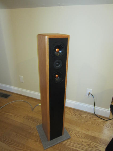
Prototype speakers have been built to demonstrate the performance of the MLTL design. Pictured are the Triton MLTL MTM speakers. The cabinets are made with cherry hardwood side and top panels (no veneer on these speakers!) and laminate covered MDF front and rear panels. The cherry hardwood and the copper color dust covers provide a stunning appearance to these speakers. The port tube and terminal plate are located on the rear of the boxes. My units use a Corian baseplate with floor pads.
Inside these cabinets are braces which strengthen the enclosure. While the cross-sectional area of this MLTL is small, my experience is that the highest pressure inside the box is at its top. Four braces are used inside the box. The first brace is under the top as the brace encircles the perimeter of the top. Just beneath the lower mid-bass a ledge brace encircles the box and a similar brace is placed at the bottom of the box. Finally, a bridge brace adds structure to the area of the tweeter. All braces are implemented with 0.75” square hardwood dowels.
For damping and frequency response smoothing the volume from below the drivers to the top of the box is filled with teased Acousta Stuf damping material. A wire screen rests on the ledge brace and retains the stuffing within this volume. The simulated stuffing density was 1 pound per cubic foot which equates to approximately 0.33 pound for each enclosure. Another damping technique is to line the internal surfaces of the panels with Sonic Barrier VE-1 vinyl sheets. Essentially, this material mass loads the panels so that any box vibration would be attenuated--these cabinets pass the knock test!
The crossover network derived by Jeff Bagby was divided into separate tweeter and mid-woofer boards. The tweeter board was mounted inside the box behind the top woofer (on the rear panel) while the mid-woofer network was placed behind the terminal plate on the front panel.
I’m just into the break-in of these speakers at this point but they have the same magic that I heard with Bryan’s speakers. Jeff’s design images like crazy and now you have additional bass extension. Hence, this design can make you grin. They reproduce music with excellent results. Only if you need bass within the 20 to 40 Hz octave, would you have to add a subwoofer.
In future postings I will more include additional details on this MLTL design.
http://meniscusaudio.com/images/Triton Kit Write up.pdf
Bryan Keane’s Triton MTM build thread is:
Jeff B's CSS Triton High Resolution Monitor
Robert Woods has a similar build thread at:
http://www.diyaudio.com/forums/mult...esolution-triton-kit-designed-jeff-bagby.html
The drivers are interesting in their size (small) yet low distortion realization. Both have patented XBL2 technology which was developed by Dr. Dan Wiggins during his tenure leading Adire Audio. Dan invented a driver design that extends the linear travel of the moving parts of the speaker so that measured distortion levels are reduced compared to standard technology.
Under the sponsorship of Creative Sound Solutions (a Canadian DIY loudspeaker parts distributor), the new XBL drivers are the CSS VWR126X mid-woofer and the LD25X tweeter. The very wide range VWR126X is a 4.5" diameter unit. Along with the XBL motor system, this driver features a woven Polypropylene cone, rubber edge, cast aluminum frame and copper dust cap. The likely driver application of the VWR126X is as a premium mid-range in multi-way systems. The LD25X tweeter features a small flange and the XBL motor system—the first for a tweeter—and is perfect for MTM and other limited baffle space designs. The distortion levels are some of the lowest measured. Both of these drivers were introduced to the market for DIYers early in 2012 and you can check several threads on DIYAudio and Parts Express Tech Talk forums threads on the Triton MTM bookshelf design.
My MTM design with the CSS drivers is realized as a mass loaded transmission line (MLTL). The MLTL configuration extracts optimum bass performance from these drivers per this size enclosure. I call MLTLs speakers with legs--the stand or base for a bookshelf speaker aren’t necessary as the MLTL yields a tall floor standing cabinet. MLTL design efforts are aided by Martin J. King’s MathCAD based worksheets.
The basic assumptions for my efforts were to retain several key elements of the Bagby Triton bookshelf design including the cabinet wide (7.5 inches), driver spacing, and the tweeter height at 35 inches as Jeff recommended. The ultimate goal was to be able to use the original Triton crossover design and its inherent baffle step correction. My contribution was to lower the bass 3 dB down frequency of the bookshelf speaker which was measured at 52 Hz by Jeff.
After working through the MJK worksheets, I have a MLTL MTM design that satisfies the design goals. It is a straight MLTL with no fold or taper so it is simple to construct. The 3 dB down frequency response is 37 Hz while the port terminus dips at 43 Hz. The outside dimensions are 7.5” wide by 8” deep and 42.5” high. Assuming 0.75” thick walls, the internal cross section dimensions are 6” wide by 6.5” deep, and 41” high. The tweeter is centered at 7.75” from the inside the top while the mid-woofers are centered at 3.5” and 12” from the top respectively. A one inch baseplate would raise the tweeter to a 35" height.
Similar to most vented box designs, the length of the port tube determines the 3 dB down frequency for the bass response of the MLTL. For the 3” diameter port tube the tube length is recommended to be 6”. During my simulations I studied various other port lengths ranging from 4.5” to 9“. For 4.5, 6, 7.5, or 9 inches lengths, the 3 dB down frequency response is 40, 37, 35, and 33 Hz, respectively. The 7.5” and 9” lengths would necessitate either a curved tube inside the enclosure or extension outside the box.
Common with vented boxes, the MLTL mid-bass drivers will have increasing cone extension at the low end of their frequency range as input power increases. For this MLTL the linear cone extension reaches maximum cone extension at an input of 30 watts at 37 Hz. For the VWR126X drivers the linear extension is specified to be 5.8 mm. The SPL produced at this limit is 105 dB. While these MLTLs aren’t subwoofers, this is an impressive SPL level for small mid-bass drivers.
Prototype speakers have been built to demonstrate the performance of the MLTL design. Pictured are the Triton MLTL MTM speakers. The cabinets are made with cherry hardwood side and top panels (no veneer on these speakers!) and laminate covered MDF front and rear panels. The cherry hardwood and the copper color dust covers provide a stunning appearance to these speakers. The port tube and terminal plate are located on the rear of the boxes. My units use a Corian baseplate with floor pads.
Inside these cabinets are braces which strengthen the enclosure. While the cross-sectional area of this MLTL is small, my experience is that the highest pressure inside the box is at its top. Four braces are used inside the box. The first brace is under the top as the brace encircles the perimeter of the top. Just beneath the lower mid-bass a ledge brace encircles the box and a similar brace is placed at the bottom of the box. Finally, a bridge brace adds structure to the area of the tweeter. All braces are implemented with 0.75” square hardwood dowels.
For damping and frequency response smoothing the volume from below the drivers to the top of the box is filled with teased Acousta Stuf damping material. A wire screen rests on the ledge brace and retains the stuffing within this volume. The simulated stuffing density was 1 pound per cubic foot which equates to approximately 0.33 pound for each enclosure. Another damping technique is to line the internal surfaces of the panels with Sonic Barrier VE-1 vinyl sheets. Essentially, this material mass loads the panels so that any box vibration would be attenuated--these cabinets pass the knock test!
The crossover network derived by Jeff Bagby was divided into separate tweeter and mid-woofer boards. The tweeter board was mounted inside the box behind the top woofer (on the rear panel) while the mid-woofer network was placed behind the terminal plate on the front panel.
I’m just into the break-in of these speakers at this point but they have the same magic that I heard with Bryan’s speakers. Jeff’s design images like crazy and now you have additional bass extension. Hence, this design can make you grin. They reproduce music with excellent results. Only if you need bass within the 20 to 40 Hz octave, would you have to add a subwoofer.
In future postings I will more include additional details on this MLTL design.
Last edited:
I presume Jim will eventually share more information on this design, possibly the modeled impedance graph. I can assure you that there will be a BR-type saddle in that graph because all TLs are inherently 4th-order systems just like a BR or vented box. Some people will stuff the life out of their TLs in order to flatten the lower-frequency peak in the saddle, which has two effects, decreasing the slope of the roll-off below the knee in the system response while also virtually killing all of the output from the mass-loading port. Thus, F3 is raised substantially, negating any bass benefits.
From what Jim has posted, this appears to be an outstanding design again that provides Jeff's excellent design with additional bass, just like Maynard Goff's ML-TL versions of Jeff's Continuum.
Paul
From what Jim has posted, this appears to be an outstanding design again that provides Jeff's excellent design with additional bass, just like Maynard Goff's ML-TL versions of Jeff's Continuum.
Paul
I would like to see the impedance response in mjk's sheets to see if it resembles traditional BR saddle.
buzzforb,
I'm using MJK's worksheets with MathCAD 8 so I have limited latitude to change the scale of the graphs. Hence, my impedance graph has a 120 ohms full range scale. The double saddle curve is there although surpressed. The peaks occur at approximately 40 Hz with 6-7 ohms and 100 Hz with a 11-12 ohms peak. Otherwise the plot follows along the 4 ohms level as it should.
Jim
That's strange, Jim. I also use MathCad 8 and I have essentially unlimited abilities for setting scale factors on the graphs, not that it matters all that much as far as this specific issue is concerned. My understanding is that it's Martin's worksheets that allow this ability, not MathCad. What version of the ML-TQWT worksheet are you using?
Paul
Paul
buzzforb,
I'm using MJK's worksheets with MathCAD 8 so I have limited latitude to change the scale of the graphs. Hence, my impedance graph has a 120 ohms full range scale. The double saddle curve is there although surpressed. The peaks occur at approximately 40 Hz with 6-7 ohms and 100 Hz with a 11-12 ohms peak. Otherwise the plot follows along the 4 ohms level as it should.
Jim
Paul.
I have the worksheets on my old XP computer and the sheet is dated 9/10/06 so it is a 2006 version. I can change the look of the graph, formating, such as the number of grid lines but no entry that I see will change the scale of the data. Autoscaling gives me 120 ohms Y axis and that seems to be unchangeable at this time. Perhaps you can suggest something off line to straighten me out on plot set-up.
Thanks,
Jim
Last edited:
Jim,
Very cool idea to "extend" on my design. I really like the execution too. I would expect these to be very impressive for the driver complement. The Tritons have some impressive bass for what they are, but it is pretty much all mid and upper bass. Of course, no one really expects a stand mounted monitor that size to dig too deep. If your design takes it another half-octave deeper then that really will be something.
I struggled a bit with a peak in the upper bass in the Tritons due to the capacitive load of the upper impedance peak due to the box tuning and the woofers resonance. I didn't add additional conjugates to flatten it, and no one seems to comment on it, so it must be pretty benign. However, if your design reduces that impedance peak magnitude then this should really flatten and extend the bass. I think your speaker has the potential of taking my design to another level, and I'm all for it.
You are right, the Tritons image like gang-busters. This must be a feature of the low distortion drivers and the lower level information retrieval they are capable of in the midrange and highs that account for this. I didn't do anything in the crossover design that I wouldn't have done in other designs, yet these still image better than any of my other speakers that I could compare them with. If you want a speaker that images, then this is the one.
I bet yours are a real joy to listen to. I hope to hear them myself sometime; I would love to hear how the MLTL performs with these little drivers. Again, nice job, and contrats on a great execution of the design.
Jeff
I'm pretty sure your 2006 version does not allow changing scales on the graphs and you'd have to "purchase" Martin's current worksheets to get that feature, which may or may not be all that valuable to you. I really like it, though, as it allows seeing some graphs with a lot more resolution and allowing you to make subtle changes for improved performance.
Paul
Paul
Paul.
I have the worksheets on my old XP computer and the sheet is dated 9/10/06 so it is a 2006 version. I can change the look of the graph, formating, such as the number of grid lines but no entry that I see will change the scale of the data. Autoscaling gives me 120 ohms Y axis and that seems to be unchangeable at this time. Perhaps you can suggest something off line to straighten me out on plot set-up.
Thanks,
Jim
Jeff, Paul, and Planet10:
Thanks for your comments Jeff and let me say that your original design gave me and other builders a good starting foundation. The Tritons really have an out of box sound that I associate with well designed and great imaging speakers.
Paul, you are likely correct that my 2006 worksheet doesn't have the functionality of later ones. I have more recent licenses with Martin so I'll check my status on that aspect. I'm thinking I need to migrate to one of my Win 7 PCs anyway so this is an opportunity for me to go to a faster, better computer for future work.
Yes, Dave the stuffing is only in the upper third of the box. I've had success with previous MLTLs with this damping scheme so that is my starting point. Do you have experience that would mandate additional damping below the drivers? If necessitated, additional damping would easy enough to add.
By bridge brace I mean two short dowels (attached on the back of the front baffle) that extend from each side to the edge of the tweeter cutout. A longer (the same width as the baffle) dowel would be glued on top of these two shorter pieces and extend over and clear the rear of the tweeter. Thus the baffle would be strengthen and have better support between the two woofers. In the bookshelf Triton MTM build threads others have essentially used dowels between the rear panel and the front panel in this same area. Now my cabinet as constructed is very solid but I'm sure that bracing improvements can always be achieved. The tradeoff is whether more extensive bracing is necessary given the cross-sectional area of this box. I'm open to any suggestions that you may have.
Jim
... the stuffing is only in the upper third of the box
... bridge brace
Thanx.
Drawing attached.
dave
Attachments
It's probably just apples to apples as for as performance is concerned, but I've found usually really good success stuffing the first (top) half of an ML-TL but at a lower density of 0.75 lb/ft3, which probably nets out to the same total amount of stuffing by weight compared to what you did (do). Now there's a secondary reason I like to use a density of 0.75 lb/ft3. Meniscus Audio sells this stuffing in batting form: Bonded Dacron. It is 1" thick and has an inherent density of 0.75 lb/ft3 (a 12" x 12" piece, which is 144 in3 in volume, weighs 1 ounce), which means no matter what shape you cut it into, it will have that density. So, you can cut it into rectangles that match the internal width and depth of the cabinet and stack up however many layers (inches) you need without having to weigh it or fluff it up.
Paul
Paul
Jeff, Paul, and Planet10:
Thanks for your comments Jeff and let me say that your original design gave me and other builders a good starting foundation. The Tritons really have an out of box sound that I associate with well designed and great imaging speakers.
Paul, you are likely correct that my 2006 worksheet doesn't have the functionality of later ones. I have more recent licenses with Martin so I'll check my status on that aspect. I'm thinking I need to migrate to one of my Win 7 PCs anyway so this is an opportunity for me to go to a faster, better computer for future work.
Yes, Dave the stuffing is only in the upper third of the box. I've had success with previous MLTLs with this damping scheme so that is my starting point. Do you have experience that would mandate additional damping below the drivers? If necessitated, additional damping would easy enough to add.
By bridge brace I mean two short dowels (attached on the back of the front baffle) that extend from each side to the edge of the tweeter cutout. A longer (the same width as the baffle) dowel would be glued on top of these two shorter pieces and extend over and clear the rear of the tweeter. Thus the baffle would be strengthen and have better support between the two woofers. In the bookshelf Triton MTM build threads others have essentially used dowels between the rear panel and the front panel in this same area. Now my cabinet as constructed is very solid but I'm sure that bracing improvements can always be achieved. The tradeoff is whether more extensive bracing is necessary given the cross-sectional area of this box. I'm open to any suggestions that you may have.
Jim
Paul,
I looked at the frequency response for various stuffing densities from 0.25 to 1.0 lb/ft3. Not a lot of difference--perhaps a 1 dB flatter response--between 0.75 and 1.0 lb/ft3 levels. The 0.75 lb/ft3batting pieces would be handy to place into a cabinet. While teasing Acousta Stuf doesn't consume that much time, the exactness of the packing density can vary between users.
Jim
Last edited:
I agree. It's so extremely convenient to use the Dacron batting from Meniscus because of being able to cut it into convenient shapes for easy installation, not having to weigh it and achieving a much more consistent density.
Paul
Paul
Paul,
I looked at the frequency response for various stuffing densities from 0.25 to 1.0 lb/ft3. Not a lot of difference--perhaps a 1 dB flatter response--between 0.75 and 1.0 lb/ft3 levels. The 0.75 lb/ft3batting pieces would be handy to place into a cabinet. While teasing Acousta Stuf doesn't consume that much time, the exactness of the packing density can vary between users.
Jim
Yes, I'm aware that extending the baffle to the ground but I've not found it to be a significant issue in previous efforts of converting bookshelf speakers to small floor standers. In the limit the bookshelf design is a good first order step toward a successful floor standing speaker design if you maintain the baffle width.
Usually, there are other room effects and such which muddy the acoustical response. In fact the response curve for this MLTL has a slight download slope (a dB or so) toward the lower frequency end of the band which will likely be beneficial to balance against additional room gain and baffle extension.
Usually, there are other room effects and such which muddy the acoustical response. In fact the response curve for this MLTL has a slight download slope (a dB or so) toward the lower frequency end of the band which will likely be beneficial to balance against additional room gain and baffle extension.
System Responses
I have attached a few key plots from the Martin King worksheets for this design. I'm working to get a rescaled impedance curve.
As with all Martin King worksheet plots the red curve is the system response curve while the blue plot is the infinite baffle equivalent.
I have attached a few key plots from the Martin King worksheets for this design. I'm working to get a rescaled impedance curve.
As with all Martin King worksheet plots the red curve is the system response curve while the blue plot is the infinite baffle equivalent.
Attachments
Last edited:
Attached are some plots of the frequency response curves when the port tube length is changed to 4.5", 6.0", 7.5", to 9" lengths from the top plot to the bottom. To me the 6.0" seems to be the optimum solution as the performance is adequate with a relative flat frequency response curve. Both the 7.5" and 9" lengths would require curving or folding inside the box or extending outside the box. For these respective lengths the F3 points 40Hz, 37 Hz, 35 Hz, and 33Hz as the tube is extended.
As with all Martin King plots, the red curve is the system response curve while the blue plot is the infinite baffle equivalent.
As with all Martin King plots, the red curve is the system response curve while the blue plot is the infinite baffle equivalent.
Attachments
- Status
- This old topic is closed. If you want to reopen this topic, contact a moderator using the "Report Post" button.
- Home
- Loudspeakers
- Multi-Way
- The Triton MTM Grows Legs--A MLTL Design