I am rebuilding the crossovers for my JBL L100T speakers. I purchased the speakers new back in the late 80's. I built new crossovers to the original specifications using the original coils and better quality capacitors. I produced a new larger PCB to accommodate the larger capacitors.
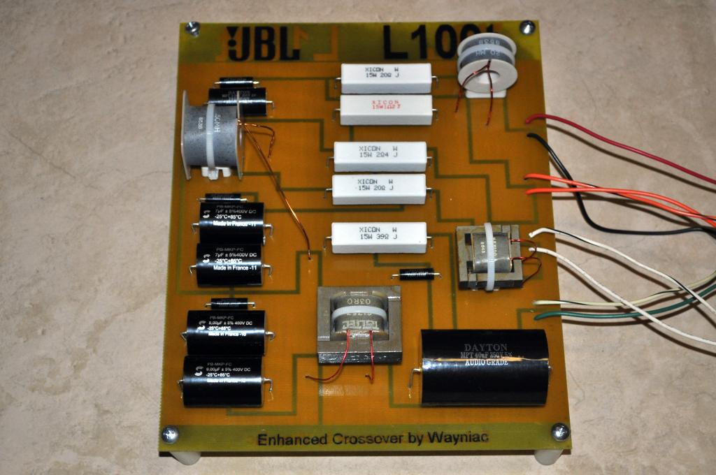
In the early 90''s, JBL "re-voiced" the L100T by changing the crossover values. I am rebuilding the crossovers now to the newer "T3" specification. This includes two coil changes and various resistor/capacitance changes.
I would like to use air-cored coils for the build, but L1, in series with the bass driver is 3.2 mH and might be a bit large and unwieldy. Any Comments?
The midrange circuit has two coils, one (L2) in series with and one (L3) parallel to the driver. If I replace coil L2 with a lower DCR part, I may change the value of R3 to compensate. The parallel coil is iron-cored and I am unsure if replacing this coil with an air-core will make any difference. If so, how do I compensate for the DCR changes?
The high frequency portion has a single coil (L4) shunted with the HF driver. This is already an air-cored coil and I will likely leave it in place unless a compelling reason to replace it arises.
Thanks for listening, I look forward to your replies.
Last edited:
North Creek makes low-DCR air core chokes. They tend to be pretty large and expensive but the ones I have made a significant improvement in sound over the other air core and iron core chokes I tried. Here's a link to their website:
North Creek Music Coil Inductors
P.S. I have no affiliation with North Creek other than having purchased a pair of 12g chokes.
North Creek Music Coil Inductors
P.S. I have no affiliation with North Creek other than having purchased a pair of 12g chokes.
You may find as have Many who play with Crossovers that silly Lo DCR in the inductor of a LF driver makes virtually NO discernable advantage. Not so in a HF unit though
As in don't sweat it, unless you are going to a notably higher DCR than the old Coil... unlikely . Just saying that: Bigger is not necessarily better") despite the Brochure babble..
despite the Brochure babble..
Simply measure your old ones as a baseline reference to emulate.
Air coils do give advantage over saturated Iron core ones. However, Few cored ones saturate at Audio frequencies... unless genuinely missapplied.
Usually a wayy too high DCR is the culprit (hair thin wire winds.. copper costs So reverting to a lower DCR gives improved performance impressions.
But, going significantly below designed DCR also gives unexpected result, just as surely as if altering the unit's value
As in don't sweat it, unless you are going to a notably higher DCR than the old Coil... unlikely . Just saying that: Bigger is not necessarily better
despite the Brochure babble..Simply measure your old ones as a baseline reference to emulate.
Air coils do give advantage over saturated Iron core ones. However, Few cored ones saturate at Audio frequencies... unless genuinely missapplied.
Usually a wayy too high DCR is the culprit (hair thin wire winds.. copper costs
So reverting to a lower DCR gives improved performance impressions. But, going significantly below designed DCR also gives unexpected result, just as surely as if altering the unit's value
Last edited:
Not so unlikely when you're replacing cored inductors with air-core. Consider a P-core or Super-Q for the big one.As in don't sweat it, unless you are going to a notably higher DCR than the old Coil... unlikely .
I am no expert, but...
The differences between the two circuits seem quite small. If you are going to try to change to the newer version then you should probably also try to use the specified DCR value for every inductor. Otherwise, your circuit might sound different than theirs and defeat your whole purpose. Compensating DCR with a series resistor is not the same as having the resistance distributed throughout the inductor, even though the typical EE's lumped-component circuit models won't show that. I have no way of knowing if the difference would be audible, though.
If you really want to track such small changes in voicing, then maybe you should consider using exactly the same type of parts the manufacturer uses.
If you do decide to use air-core ("they say" that iron cores might give hysteresis-induced distortion, not just the risk of saturation, which is probably not worth worrying about), but can't find the right combination of L and DCR values for sale, you could wind an air-core coil to get any reasonable combination of L and R. You just have to change the shape and wire gauge appropriately. There are coil calculators that you can use, to try to get it right. But you might have to run quite a few iterations, tweaking in between, before you find the right combination of coil dimensions and wire gauge.
Here is a pretty good one that will do what you need:
Pronine Electronics Design - Multilayer Air Core Inductor Calculator
Also, if you search the North Creek site thoroughly, you will find an important paragraph about diy construction of air core coils.
They sell air-core inductors at those two diy speaker supply places that are mentioned a lot, and other places. So you might want to check around first to see if you can get lucky on the values.
Not so unlikely when you're replacing cored inductors with air-core. Consider a P-core or Super-Q for the big one.
Erm you read it Back asswards Mate
PS: Look at Solen.ca (even if only for reference/educational reasons) they have ample supply of proven quality air coils. They also state the DCR of Each coil. Making it quite simple (albeit a bit tedious) to find reasonably close to oem values thereby avoiding wasting $$ for No advantage whatsoever.
personally I would say that the L3 would make the biggest difference (which may be still quite small) if the DCR value is changed. It is part of a notch filter, and my experience with notch filters has been that they are much more sensitive to component variations than other areas of crossovers.
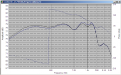
Given that, I just simmed one of my crossover inductors (in a 1.3K notch) with an increase in DCR from the actual 100m ohms to 300m ohms, and it resulted in approximately 0.5 db change (less cut) in the notch, and a bit lower overall spl at frequencies below the notch frequency (due to the higher DCR).
Attached a picture showing the variation. Note that these sims are very accurate. Blue is the higher DCR.
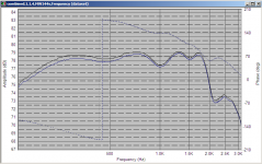
Second picture is with the normal values for the notch, but the DCR of the series coil increased from the actual (black) value of 117m ohms to 300m ohms.
Tony.
Given that, I just simmed one of my crossover inductors (in a 1.3K notch) with an increase in DCR from the actual 100m ohms to 300m ohms, and it resulted in approximately 0.5 db change (less cut) in the notch, and a bit lower overall spl at frequencies below the notch frequency (due to the higher DCR).
Attached a picture showing the variation. Note that these sims are very accurate. Blue is the higher DCR.
Second picture is with the normal values for the notch, but the DCR of the series coil increased from the actual (black) value of 117m ohms to 300m ohms.
Tony.
Attachments
- Status
- This old topic is closed. If you want to reopen this topic, contact a moderator using the "Report Post" button.
- Home
- Loudspeakers
- Multi-Way
- Crossover Inductor DCR Values and General Crossover Advice