Hi greyhnd, from the pictures you supplied it looks like there is only one component in the crossover, a capacitor. If this is the case then it will be on the tweeter, and the woofers will be running full range.
Since you have two woofers and the speakers are rated at 8 ohms nominal impedance, there are two possibilities.
1. the existing woofers are 4 ohms impedance each and wired in series to give 8 ohms total.
2. the existing woofers are 16 ohms impedance each and wired in parallel to give 8 ohms total.
I guess there is another possibility and that is that the impedance rating on the back of the box is an arbitrary figure marketing chose")
If the drivers are wired in series when you swap in one (or both) of the new woofers the impedance will rise to 12 ohms or 16 ohms which will mean higher resistance and therefore lower sound output. for a given drive voltage. (depending on efficiency differences between the woofers).
If the original drivers were 16 ohms and wired in parallel, then when you add a single 8 ohm driver you will get uneven sharing of the current between the drivers, with more of the current going to the lower impedance driver.
If there was a coil on the woofers (in the crossover) then yes changes in impedance would change the frequency at which the crossover cuts in.
Tony,.
Since you have two woofers and the speakers are rated at 8 ohms nominal impedance, there are two possibilities.
1. the existing woofers are 4 ohms impedance each and wired in series to give 8 ohms total.
2. the existing woofers are 16 ohms impedance each and wired in parallel to give 8 ohms total.
I guess there is another possibility and that is that the impedance rating on the back of the box is an arbitrary figure marketing chose
If the drivers are wired in series when you swap in one (or both) of the new woofers the impedance will rise to 12 ohms or 16 ohms which will mean higher resistance and therefore lower sound output. for a given drive voltage. (depending on efficiency differences between the woofers).
If the original drivers were 16 ohms and wired in parallel, then when you add a single 8 ohm driver you will get uneven sharing of the current between the drivers, with more of the current going to the lower impedance driver.
If there was a coil on the woofers (in the crossover) then yes changes in impedance would change the frequency at which the crossover cuts in.
Tony,.
Hi Tony and thanks for your reply.
After reading your post, I'm not exactly sure the easiest and/or best way to solve the problem. One of my concerns is that the Lepai T-amp I'm powering the speakers with is rated from 4 - 8 Ohms, and it puts out 13W @ 8ohms and 20W @ 4ohms. If I'm not mistaken, the amp will see an 8ohm load regardless on the box that currently has both factory speakers? So if the MCM speakers are both 8 ohms, where does that put me? If I'd known then what I know now I would've ordered 4 ohm replacements.
I hate like the devil to invest a bunch of money in this project, but I'm also not willing to accept defeat. Stubborn perhaps or foolhardy. The speakar with both the MCM drivers installed actually sounds "fuller" then the stock speaker. Do I need to wire the speakers to the crossover differently, or replace/modify the crossover that's in place? I have no problem experimenting, but I'm not smart enough to figure out what direction to go.
My goal is to use the speakers with the new TV I have ordered. I intend to power them with the t-amp if that makes a difference.
Lepai T-amp I'm powering the speakers with is rated from 4 - 8 Ohms, and it puts out 13W @ 8ohms and 20W @ 4ohms.
T2020?
dave
Hi greyhnd as a start so we know what we are dealing with, if you have a multimeter, put it in ohms mode and measure the resistance of one of the MCM woofers (disconnected) and also measure the resistance of one of the kenwoods.
The next step is to trace out exactly where the wires connect from your panel/crossover to the speakers. It looks from the pictures like the woofers don't have any crossover components, but I'm not certain about that.
If the speakers turn out to be wired in series currently, you should be able to wire them in parallel instead though the resulting impedance will be nominally 4 ohms. The dc resistance of the new MCM's should give a pretty good indication as to what the minimum impedance would be.
Tony.
Dave - Yes sir, that's the little Lepai t-amp I'm using.
6 watts into 8, 10 into 4.
dave
Tony - Yes I do in fact have a multimeter. I'll get the measurements on both the Kenwood and the MCM speakers. I'll also see if I can diagram the way the wiring is. My freehand drawing skills on the computer are poor and that's being generous, but I'll see if I can make something that will be helpful.
Dave - When you indicate 6W @ 8 ohms and 10W @ 4ohms, I assume you mean per speaker? The little sucker gets loud, but several years ago I had a tube amp that put out about 6 watts and I used it to power some Dahlquist DCM-9c studio monitors. It never lacked in performance.
Dave - When you indicate 6W @ 8 ohms and 10W @ 4ohms, I assume you mean per speaker? The little sucker gets loud, but several years ago I had a tube amp that put out about 6 watts and I used it to power some Dahlquist DCM-9c studio monitors. It never lacked in performance.
Okay guys, I checked the ohms and made a diagram of the crossover, such as it is.
The Kenwood woofers measured between 14 - 15 ohms. The MCM woofers (both) measured dead on at 7 ohms.
As far as the crossover is concerned it's about as simple as I've ever looked at. As you can see in my diagram, the negative wires from both woofers and the tweeter go directly to the negative terminal connector. The woofers positive wires go directly to the positive terminal connector. The tweeter positive passes through the cap then on to the positive terminal connector. I still haven't been able to determine the values for that little cap. I can't see it well enough to get the numbers.

Hopefully this will suffice. If still unclear I'll do as Tony suggested and hand draw one and take a digital pic.
The Kenwood woofers measured between 14 - 15 ohms. The MCM woofers (both) measured dead on at 7 ohms.
As far as the crossover is concerned it's about as simple as I've ever looked at. As you can see in my diagram, the negative wires from both woofers and the tweeter go directly to the negative terminal connector. The woofers positive wires go directly to the positive terminal connector. The tweeter positive passes through the cap then on to the positive terminal connector. I still haven't been able to determine the values for that little cap. I can't see it well enough to get the numbers.
Hopefully this will suffice. If still unclear I'll do as Tony suggested and hand draw one and take a digital pic.
Perfectly clear So when you wire in both of the MCM's you are going to get an impedance of nominally 4 ohms, with a dip to possibly as low as 3.5 ohms. This is not too bad. I don't know anything about the lepai amps, but suspect that most amps that are rated to 4 ohms should be able to cope with that.
So I think that wiring the speakers as per the originals should be fine, and is the most sensible way to do it (without getting into the benefits of putting a proper crossover on the drivers rather than running full range)..
The next thing to think about is how to optimize the response of the drivers.
I'm assuming that "The cabinet dimensions are 14.5" H x 6.75" W x 6.75" D" is external dimensions? Allowing for 12mm walls I get an internal volume of around 7.5L (not allowing for drivers. So around 6.8L perhaps.
That gives a starting point for modeling to see what might be workable. Reality is though that a new cabinet will probably give the best results.
Tony.
So when you wire in both of the MCM's you are going to get an impedance of nominally 4 ohms, with a dip to possibly as low as 3.5 ohms. This is not too bad. I don't know anything about the lepai amps, but suspect that most amps that are rated to 4 ohms should be able to cope with that. So I think that wiring the speakers as per the originals should be fine, and is the most sensible way to do it (without getting into the benefits of putting a proper crossover on the drivers rather than running full range)..
The next thing to think about is how to optimize the response of the drivers.
I'm assuming that "The cabinet dimensions are 14.5" H x 6.75" W x 6.75" D" is external dimensions? Allowing for 12mm walls I get an internal volume of around 7.5L (not allowing for drivers. So around 6.8L perhaps.
That gives a starting point for modeling to see what might be workable. Reality is though that a new cabinet will probably give the best results.
Tony.
Last edited:
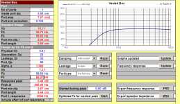
I just modeled based on the assumed size above (and an estimated sd of 50cm). Attached is a graph comparing sealed with vented in 6.8L enclosure.
I've also included step response and excursion graphs. Step response looks very good!
This all assumes that the volume I modeled with is accurate (which it probably isn't). The box tuning was 58.5 Hz. port was 3cm diameter and 6.44cm long. This could probably be placed in the back of the box. last attachment shows the unibox parameters.
Tony.
Attachments
The Diagram makes sense relative to the prior data we've been give. The resistances you are measuring are consistent with the DC resistance of 16 drivers and an 8 ohms Speaker System.
However, 16 ohms speaker are very hard to find today. Not impossible, but difficult.
My advice would be, restore the design to its original configuration, or accept that the best you can do is a resulting 4 speaker system (two 8 ohms in parallel).
There is one other alternative, which is two 4 ohm bass drivers wired in series. But, two in series has the same acoustical output as a single bass driver*, but it will handle twices as much power.
*Each driver in series receives half the power, but because there are two of them, you move twice the air. Do the Total is in essence ... 2/2 = 1. Two drivers in series equals the output level of one driver, but it has other advantages like handling twice the power and having half the excursion.
There are Dual Voice Coil speakers, that can be effectively wired as 4 ohms or 16 ohms, but I've never seen one in a 4" size. They tend to run 8" up to 15".
So, I think those are you choices, either accept them as they are, or add two new bass drivers to each speaker and wire them in series.
Steve/bluewizard
There is another option as well forget the kenwood cabinets and build some new "designed for these drivers" boxes with a single MCM driver and a tweeter in each. Either use the kenwood tweeters or get something else. Zaph writes a bit about them here and has measurements as well.
Tony.
forget the kenwood cabinets and build some new "designed for these drivers" boxes with a single MCM driver and a tweeter in each. Either use the kenwood tweeters or get something else. Zaph writes a bit about them here and has measurements as well. Tony.
Tony - You were correct in your assumption a few posts earlier about the box dimensions, as I had measured them from inside the best I could. I also copied the driver specs from the MCM website and they are attached below, FWIW.
View attachment mcm_woofer_specs.txt
Your most recent post concerning a new box is appealing. I have a couple extra tweeters here, although without looking I'm not sure what brand or other specs. The only things for certain is they are 4 ohm and 1" silk dome.
I downloaded both Unibox and WinISD and will have to enter the driver specs in both since neither have my speaker in the database.
Steve - If I decide to stay with the original cabinets and speaker configuration I'll invest in a couple more of the MCM's and let it go at that. And using the little Lepai amp for power I don't think I'll be in jeopardy of overpowering them.
oh hang on you measured internally? I subtracted 24mm from each dimention (assuing 12mm wall thickness). So the volume I used is off.
Yes put in the T/S parameters manually. Zaph has some on his site as well (though they don't look much like the manufacturers specs). I used 50 sq cm for the Sd (based on the specs of another 4" woofer). Zaph has 52cm so that is probably more accurate.
Tony.
Yes put in the T/S parameters manually. Zaph has some on his site as well (though they don't look much like the manufacturers specs). I used 50 sq cm for the Sd (based on the specs of another 4" woofer). Zaph has 52cm so that is probably more accurate.
Tony.
Tony - I have a question about using the MCM woofers wired in series and the Kenwood tweeter. If I use the MCM's x2 in series then the amp will see a 4ohm load, correct? If the Kenwood tweeter is 8ohm and the xover is for 8ohms, such as it is, can I just leave things as they are? What would happen if I substituted the 4ohm tweeters I have here if the xovers are for 8ohms? I seem to be over thinking this.
The idea of using one of the MCM's in a new box with the Kenwood tweeter is beginning to look better the more I think about it. If I can get the box volume close in a vented arrangement is what I'm leaning toward.
I also have a good bit of 10" "sonotube" that I might experiment with. I read somewhere of a person using it with a small woofer and tweeter combo and getting good results. I used it for my sub enclosure in my Jeep and that sub hits pretty darn hard. Just tossing ideas around.
Hi greyhnd, I think you meant if you wire the woofers in parallel. in parallel you will get 4 ohms. In series you will get 16 ohms.
With respect to the tweeter, if you substitute a 4 ohm tweeter for your 8 ohm one, you will theoretically need to double the capacitance to keep the same crossover frequency (I say theoretically because it depends on the actual impedance curves of the individual tweeters)
There isn't an issue having an 8 ohm tweeter and four ohm woofer provided that levels are similar, and crossover components are tailored to the individual drivers requirements.
Your current kenwood crossover is about as simple as it gets, and can almost definitely be improved.
The original kenwood drivers may have a very smooth rollof allowing them to run full range. The MCM's have some breakup due to the metal cones, which could probably benefit from a notch filter, if run full range (based on zaph's measurements)
Tony.
I do wonder quite what problem is being solved here. Do you really know where you are going on this?
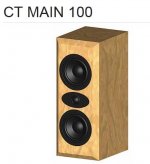
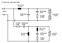
Here, for interest and education is an old Visaton MTM kit using 2X 40hm paper woofers. A lowish 2kHz crossover which needs some consequent allowance for the nearby Fs 1500Hz tweeter resonance. Hence the unusual LCR tweeter notch.
CT MAIN 100
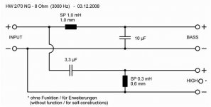
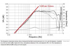
The whole thing is 8 ohms overall. The 1.5mH bafflestep coil boosts the relative bass level at the expense of pure efficiency. As ever, losing efficiency creates a smoother overall sound. For comparison, I enclose the 3Khz standard Visaton crossover which may need some simple tweeter attenuation. And a Fs 1700Hz SEAS tweeter so you might spot the typical Fs resonance. Since you have no idea of the specs of the tweeter, you can just sidestep the Fs resonance with a higher crossover point.
Despite what people say, a rough and ready crossover with well behaved drivers can work well. Unfortunately, metal drivers are rarely well behaved, tending to harsh cone breakup around 5kHz.
You will notice that the capacitor value doubles with the 2kHz crossover over the 3kHz crossover. This is because the crossover point changes roughly as the SQUARE ROOT of the tweeter capacitor and bass coil value.
Here, for interest and education is an old Visaton MTM kit using 2X 40hm paper woofers. A lowish 2kHz crossover which needs some consequent allowance for the nearby Fs 1500Hz tweeter resonance. Hence the unusual LCR tweeter notch.
CT MAIN 100
The whole thing is 8 ohms overall. The 1.5mH bafflestep coil boosts the relative bass level at the expense of pure efficiency. As ever, losing efficiency creates a smoother overall sound. For comparison, I enclose the 3Khz standard Visaton crossover which may need some simple tweeter attenuation. And a Fs 1700Hz SEAS tweeter so you might spot the typical Fs resonance. Since you have no idea of the specs of the tweeter, you can just sidestep the Fs resonance with a higher crossover point.
Despite what people say, a rough and ready crossover with well behaved drivers can work well. Unfortunately, metal drivers are rarely well behaved, tending to harsh cone breakup around 5kHz.
You will notice that the capacitor value doubles with the 2kHz crossover over the 3kHz crossover. This is because the crossover point changes roughly as the SQUARE ROOT of the tweeter capacitor and bass coil value.
Attachments
Tony - I did in fact mean to say wired in parallel. I just now moved one of the MCM drivers to each of the boxes and disconnected the Kenwood woofer in each. So at this point I have the MCM woofer and the Kenwood tweeter in each. Will probably sound like crap, but it's only an experiment.
From my calculations I think the volume of the Kenwood boxes is roughly 0.38 cu ft. I'm curious what they'll sound like with a single woofer/tweeter setup. I might remove the remaining Kenwood woofer and screw a piece of wood over the hole and see if that makes a difference. Just looking for a starting point for the correct volume.
system7 - Thank you sir for the info and diagrams. I'm thinking your suggestion for a proper crossover is a good one. When I started this project I didn't intend to take beyond getting a bit more bass response. That is still my goal, but deciding how to go about getting there is where I am now.
Everyone here has been very helpful and that is more than I expected or probably deserve. Updates a bit later.
- Status
- This old topic is closed. If you want to reopen this topic, contact a moderator using the "Report Post" button.
- Home
- Loudspeakers
- Multi-Way
- Replaced speakers and results not as expected.