Hi all, new to the forums. I have an old set of 3 way speakers with 12" 4" and 3" drivers...They are quite old and sound terrible.There is no high end.
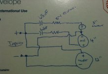
The circuit in question (attached) is the crossover that these speakers use....It looks to me much like a zobel impedance matching circuit, but its not...Any ideas?
The circuit in question (attached) is the crossover that these speakers use....It looks to me much like a zobel impedance matching circuit, but its not...Any ideas?
Attachments
Welcome to the forum.
It's not a Zobel, a Zobel circuit would be in parallel with the drivers, not in series like this one. Same parts, tho - you are right about that.
What you have there is a 1st order low-pass with attenuation on both the tweeter and the mid. A very simple crossover. Nothing on the woofer.
You could try a lower value resistor on the tweeter for more high end. Also try that on the midrange driver, it may have enough hgh end t make the difference you are after.
Yeah, that would make sense. 1.5 Ohm and 2.5 Ohm are reasonable values for a circuit like this. Strange about the K.
You could get yourself some small value resistors, like 3 or 4 ohm and put them in parallel with what you've got. That will lower the resistance and thus less attenuation. Or even put them in series with the mid, to see if reducing the midrange make the balance better. Us a simple jumper to by pass the resistors and listen the the difference.
You might run the risk of burning up the tweeter by lowering the resistance, more current will flow, but if these are truly awful, why not take the time to play around and learn what crossovers do and how they work. Listen for the changes that substituting different part values can bring.
It's a very cheap speaker, so nothing wrong with experimenting with the crossover, but expect no miracle.
The capacitor is to block low frequency (bass). The smaller the capacitance, the higher the frequency threshold (treble) you send to the tweeter/midrange.
The resistor is like volume control. To balance the level of SPL between 3 drivers. Bigger resistance, less volume. Lower resistance, more volume, might break the tweeter or at least you may hear distorted sound because the driver cannot handle the extra power well.
Those are the basics for experimentation. Real speaker design is more complex than that. Even with such a cheap crossover approach, if done properly (taking into accounts at least phase issue) can make a good sounding speaker. The usual problem is that adding tweeter will not always improve the trebles when the tweeter is not in phase with the woofer.
It's the tolerance : J, K ,.....Yeah, that would make sense. 1.5 Ohm and 2.5 Ohm are reasonable values for a circuit like this. Strange about the K.
")
The first thing to do is to limit woofer's emission above 1 KHz ,which is a thing that the woofer does by itself due to the natural
limits of a big cone to vibrate at such high frequency.
Then to find a real midrange speaker- or a so-called full range
A dome tweeter would then close the circle and bring to life the hidden high frequencies.
So : a big coil ( 1-3 mH) for lowpass ( it depends on driver's Z ) and some 33-47-68 uF bipolar caps for high-pass;just
for starting ...
Last edited:
Thanks for the responses. It leads me to another question...If you can simply add and remove resistors to speakers, why then can you not take a 4ohm speaker and add a 4ohm resistor in series to make an 8ohm speaker to work with your amp?
Of course you can do that. But you will burn 50% of the input power in the resistor and double the Qts of the woofer.
Ah yes, of course! I'm too stuck on resistors with color bands. Don't see that on power resistors, so you?It's the tolerance : J, K ,......
Thanks.- Status
- This old topic is closed. If you want to reopen this topic, contact a moderator using the "Report Post" button.
- Home
- Loudspeakers
- Multi-Way
- Can't Identify This Circuit