Hello Guys.
I've been busy on designing a speaker in Boxsim.
The basic Idea is to make a speaker with the best possible value for money, hence the name Top Dollar. Right now the box and drivers are set. I choose two W170s in parallel as midwoofers and the ferro fluid cooled G25FFL as tweeter, both from Visaton. In general I like the sound of coated paper and soft dome drivers, if crossed properly their sounds match up very nicely IMHO. I Put them in a 30L box with a port tuning freq. of 32Hz. The total can be built for around €600,-, cost of the drivers alone is €280,-
Here is a pic of the design.

Now I end up with a dilemma. I made two possible crossovers.
This first one is a series design I used from a Troels Gravesen project and optimised myself with help from the XO-optimiser built in Boxsim. I mainly just removed a few networks I found obsolete and kept running the XO-optimiser until it looked decent. I love it's simplicity")
Freq/Imp response:
 Freq res.png")
Crossover:
 Crossover.png")
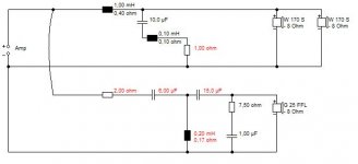
The second option a calculated myself from scratch. It's an 2nd order parralel crossover with tweeter resonance compensation, sens. matching and a zobel on the woofers. The Q was calculated at 0,5 for a Linkwitz slope. I ran it trough the boxsim optimiser and I'm quite content with it. The impendance plot is not as flat as I hoped though, I'm starting to think Boxsim has little priority with keeping it flat. Also the green peak of the tweeter worries me a bit.
Freq/imp response:
 Freq res.png")
Crossover:
 Crossover.png")
Which one would you guys build?
Some sidenotes on Boxsim:
I've been busy on designing a speaker in Boxsim.
The basic Idea is to make a speaker with the best possible value for money, hence the name Top Dollar. Right now the box and drivers are set. I choose two W170s in parallel as midwoofers and the ferro fluid cooled G25FFL as tweeter, both from Visaton. In general I like the sound of coated paper and soft dome drivers, if crossed properly their sounds match up very nicely IMHO. I Put them in a 30L box with a port tuning freq. of 32Hz. The total can be built for around €600,-, cost of the drivers alone is €280,-
Here is a pic of the design.
Now I end up with a dilemma. I made two possible crossovers.
This first one is a series design I used from a Troels Gravesen project and optimised myself with help from the XO-optimiser built in Boxsim. I mainly just removed a few networks I found obsolete and kept running the XO-optimiser until it looked decent. I love it's simplicity
Freq/Imp response:
Crossover:
The second option a calculated myself from scratch. It's an 2nd order parralel crossover with tweeter resonance compensation, sens. matching and a zobel on the woofers. The Q was calculated at 0,5 for a Linkwitz slope. I ran it trough the boxsim optimiser and I'm quite content with it. The impendance plot is not as flat as I hoped though, I'm starting to think Boxsim has little priority with keeping it flat. Also the green peak of the tweeter worries me a bit.
Freq/imp response:
Crossover:
Which one would you guys build?
Some sidenotes on Boxsim:
- It tends to give quite big impendance swings in the freq spectrum when running the optimiser. In general the Freq response gets better but I worry the bigger impendance swings will mess up the speaker IRL. I strongly favour an as flat as possible imp plot. What do you guys think?
- Looking in the Boxsim database website I see quite a lot of designs with big Impendance swings. Are they badly designed or is it just not that big of a deal?
- Is there a place where I can find Freq, phase and imp response plots for drivers from different vendors to load in boxsim?
Last edited:
I did this one a while back when I was interested in a Morel MTM design. I found a little notch on the bass worked wonders for phase and reducing cone breakup from the woofers. Since it is a Qts=0.5 woofer with Vas of 38L, a big closed box made sense to me. Maybe 50L.
I don't really see what you are trying to do with the undamped tweeter notch. It's plain wrong for a Fs 1600Hz tweeter.
For all that, the tweeter does geta bit of a hammering in this design, but that's how it goes with loud MTM designs around 90dB SPL. In the end you build stuff because it appeals to you. I certainly wouldn't worry about some impedance peaks, transistor amps don't mind them. Just as long as it doesn't go too low.
Tricky blighters, serial crossovers. Don't think these drivers are suitable. Boxsim is limited in importing other drivers data, but it can be done.
Attachments
You need measurement gear if you want to design your own speaker. Boxsim is a nice tool but it is not accurate enough for a "final" design. I've seen many simulations with Visaton drivers which differ from measurements by > 1 dB, which is a lot if it covers an octave or more.
As for value for money, I'd choose a Seas tweeter. The woofer is ok but I think the price/performance ratio of the Peerless SLS line is better. You could also look on the web for low-budget designs. There's lots of those.
As for value for money, I'd choose a Seas tweeter. The woofer is ok but I think the price/performance ratio of the Peerless SLS line is better. You could also look on the web for low-budget designs. There's lots of those.
They share the same 30L housingThe simulation seems to assume a volume of 30 litres per driver. Therefore your speaker will need a total volume of 60 litres.
I'm planning to do so indeed, do you know a good place near Enschede for some cheap but good starting equipment?You need measurement gear if you want to design your own speaker.
I did this one a while back when I was interested in a Morel MTM design. I found a little notch on the bass worked wonders for phase and reducing cone breakup from the woofers. Since it is a Qts=0.5 woofer with Vas of 38L, a big closed box made sense to me. Maybe 50L.
I don't really see what you are trying to do with the undamped tweeter notch. It's plain wrong for a Fs 1600Hz tweeter.
For all that, the tweeter does geta bit of a hammering in this design, but that's how it goes with loud MTM designs around 90dB SPL. In the end you build stuff because it appeals to you. I certainly wouldn't worry about some impedance peaks, transistor amps don't mind them. Just as long as it doesn't go too low.
Tricky blighters, serial crossovers. Don't think these drivers are suitable. Boxsim is limited in importing other drivers data, but it can be done.
Thanks for the tips!
I'll try your crossover, I'm curious
-I worry about impendance peaks because when you cross at that point the rising impendance will shift the crossoverpoint. Or am I mistaken?
-What makes a driver suitable for series networks in comparison with parallel? I always thought the drivers didn't matter.
-I tried dampening the tweeter resonance peak but for some reason it didn't work. I'll redo the math soon.
W 170 S - 8 Ohm
30-40L reflex or closed box looks OK.
That circuit I showed you is not a million miles from the SEAS Odin 3 which uses metal woofers, but the principle of notching the woofer still applies.
Serial filters are just picky about drivers. Polycones work best. Crossover point is not affected by impedance, though a valve amplifier might behave differently. I would do things differently if designing for a SET valve amplifier with a highish output impedance. I'm not sure you should even try to notch the tweeter Fs resonance. Not necessary really.
W 170 S - 8 Ohm
That circuit I showed you is not a million miles from the SEAS Odin 3 which uses metal woofers, but the principle of notching the woofer still applies.
That circuit works quite well indeed!
I only added a little resistor to up the minimum impendance to 4Ohm and damped the tweeter a tiny bit. I think it's the best so far, I hope if you don't mind me using it?
Freq response:
 Freq res.png")
Crossover:
 Crossover.png")
Worthy a build and a measure?
They share the same 30L housing
This means that each driver should have 15 litres each in Boxsim. For a W170S it would be better to use one and put it in 30 litres BR.
As for measurement gear, I've got a Dayton EMM-6 microphone which I've calibrated (the original calibration was a mess). You'll also need a decent sound card (preferably with ASIO support) and mic amp with phantom power. If you want to measure impedance you could build a simple circuit with a few resistors yourself.
I've gotta agree that going below 40L here might get a bit problematic. You can reduce the bass bafflestep coil to compensate, but that would have knock-on effects elsewhere.
Adding resistance (that 0.33R) around the bass coil has effects too. It increases the overall Qe of the driver and makes the bass woolly. Since you are around 4 ohms already, you really don't want more than 0.4 ohms on the bass coil to avoid making the box even bigger.
Explained here by the brilliant Morgan Jones: http://www.diyaudio.com/forums/diyaudio-com-articles/158899-arpeggio-loudspeaker.html
But a single bass would be rather dull, wouldn't it? Not D'Appolito at all.
Mate, I have no patent on these circuits. Feel free to use them.
I redesigned the box to 50L and removed the 0,33Ohm resistance on the woofer.
Then optimised for a Port tuning frequency of 32Hz. Going for 1 bass is too dull for me indeed and I wanted to beep the 2x30L response so redesigning to 50L (2x25l connected) really was the only option.
Ran it trough Boxsim and it gave me pretty much the same reponse and the new design actually hardly looks that much bigger.
I expect to spend around €70,- on crossover parts:
-Jantzen Cross-Caps
-Jantzen 1mm air coil inductors
-SupremeES resistors (they don't cost that much extra anyways).
On drivers €280,- and the Box I'll try to keep down to €300,- with a 31mm front baffle and 20mm for the rest, good birch plywood all the way. The back will be padded with a 5cm layer of wool and the front and side panels will get a layer of lead bitumen and a bit of felt around the drivers.
Which brings me to a total of around €700,- for a pair.
What do you guys think of it? Worth the trouble?
Thanks for the help, I learned a lot tonight
Last edited:
This is all looking very nice. I was looking at Troels' Vifa C17WH tower which is along the same lines.
Vifa C17WH-
He suggests some (window?) braces to break up the big panels. Port on the middle of the back in his design, as it goes. Certainly putting it near the floor boosts the bass thorough floor reinforcement, so something to ponder there. People often put some fluff in the bottom third of floorstanders to damp the long resonance.
Probably the size of your listening room is a big consideration. But you've doubtless got tone controls. Go for it!
This is all looking very nice. I was looking at Troels' Vifa C17WH tower which is along the same lines.
Vifa C17WH-
He suggests some (window?) braces to break up the big panels. Port on the middle of the back in his design, as it goes. Certainly putting it near the floor boosts the bass thorough floor reinforcement, so something to ponder there. People often put some fluff in the bottom third of floorstanders to damp the long resonance.
Probably the size of your listening room is a big consideration. But you've doubtless got tone controls. Go for it!
I love Troels his website. It's such a nice one to read and you learn a bunch from him.
I have quite a big listening room so a bit of volume wouldn't hurt. I certainly won't be lacking bass with this design in my room.
I've already incorporated two window braces in my design. Here are the two versions next to each other. The left one is the 50L version, I'm glad it hardly looks much bigger as the 30L version on the right

Just for good measure, the 50L version:
Freq.
 Freq res.png")
Cross.
 Crossover.png")
Frankly, I can only encourage you to have a go at this D'Appolito design.
0.18mH or a preferred value of 0.2mH is going to make almost no difference whatsoever.
Within a couple of minutes, your ears compensate. What I do think is this is a pretty easy load for almost any transistor amp. A Riga Brio-R will have no difficulty with this.
Cabinets are an interesting detail. I currently admire the Harbeth approach.
http://www.diyaudio.com/forums/multi-way/223174-interesting-read-i-found-lossy-cabinet-designs-harbeth.html#post3234256
Do let us know how you get on. I really ought to do some of my own stuff too. Spend FAR too much time here, and not enough time building.
-I worry about impendance peaks because when you cross at that point the rising impendance will shift the crossoverpoint. Or am I mistaken?
Absolutely, the impedance of both drivers need to be relatively flat through the cross-over frequency band, perhaps with a second order cross-over network, an octave above and below the cross-over frequency. Otherwise, crossing over is going to work out badly.
So what is the cross-over frequency of your 50L design? -Easier to ask then to extrapolate from your network.
Regards,
Pete
The crossover -6dB point on the treble filter is 3kHz in post #13's frequency response plot. What's hard about that?Absolutely, the impedance of both drivers need to be relatively flat through the cross-over frequency band, perhaps with a second order cross-over network, an octave above and below the cross-over frequency. Otherwise, crossing over is going to work out badly.
So what is the cross-over frequency of your 50L design? -Easier to ask then to extrapolate from your network.
Regards,
Pete
I don't know of a single reactive crossover that doesn't have impedance peaks. You can of course use low inductance drivers and lots of resistors and Zobel networks in a crosssover for a lower, flatter impedance as in the weird Sonus Faber Extrema loudspeaker.
This design is just a piece of pure audio nonsense, since the treble filter's series resistor soaks up huge amounts of amplifier power needlessly. I am being polite in the following post to spare someone's feelings, but I'm saying that it is a STUPID design.
http://www.diyaudio.com/forums/multi-way/206843-sreten-speakerman-go-series-xos-57.html#post3047689
The original XO frequency was 1800Hz but I fidgetted quite a bit by just changing values by hand and seeing the reaction or running the optimiser. I've also always learned that the imp curve has to be flat as possible in the XO region, for some reason the resonance compensation circuit I calculated had no effect, I'll redo it soon because I too don't like the peak near the XO region.Absolutely, the impedance of both drivers need to be relatively flat through the cross-over frequency band, perhaps with a second order cross-over network, an octave above and below the cross-over frequency. Otherwise, crossing over is going to work out badly.
So what is the cross-over frequency of your 50L design? -Easier to ask then to extrapolate from your network.
Regards,
Pete
Despite what System7 says the XO isn't easily deductable because you have to first calculate the total impendance of the two drivers including the networks combined with them. It's supposed to be around 2000Hz, but I was thinking about crossing it higher anyways to make life a tiny bit easier on the tweeter, but not too far because the two midwoofers have some ugly breakups at higher frequencies that I don't want anywhere near the audible region.
Despite what System7 says the XO isn't easily deductable because you have to first calculate the total impendance of the two drivers including the networks combined with them.
Assuming a parallel cross-over network, then the high-pass and low-pass sections operate in parallel circuit, that is, there is no interaction between them. That is what I think, anyway, so your above statement is puzzling to me.
Ideally, the procedure that I would follow would be:
(1) Get the impedance of the tweeter and woofer in the crossover region to be as flat as possible.
(2)If you want to put extra effort into the project to get the best results, this involves actual, physical measurement of the flattened impedance of the drivers in the cross-over region.
(3) The values of inductance and capacitance of the high- and low-pass filters then follow from the measured impedance of the drivers at the cross-over frequency, and the cross-over frequency.
Very straight-forward, I would say, or not?
Pete
Very straight-forward, I would say, or not?
Pete
Hi Pete, it is indeed.
The problem is that, eventhough I've been reading and pondering for a long time. This is my kick off project, it's not my first design, but it's the first that is buildable for moderate costs and where I'm confident enough it'll sound the way I like, or close at least. Sure I want to measure it someday. I want to go on measuring and building speakers. This one I want to simulate into "perfection" first from my comfy chair, then build it, then get the kit to measure it and in the end enjoy my speakers while I build and measure more.
I know it's best to start with good measuring kit. But the way I see it now I'd rather spend the money on actual speaker material to get going and perfect it further from there when I buy proper kit. From what I know and have read Boxsim is a complete, intuitive and quite capable program. It's not profeesional software but it gives a starter like me time and means to potter around and have some certainty once the built speaker gets measured it won't be miles off. For now that's enough for me, the box and the units won't change and trying a new, optimised, crossover later on will only make the build more rewarding in my eyes.
I have a pair of Tannoys I really like so I can patiently tune these further in the future without having to miss out on good quality music
Oh, okay, I think that I understand now. You are referring to the red (impedance) trace, impedance as seen by the amplifier "looking into" the speaker system. That is, the graph of your post # 13. Assuming that you are using a solid-state amp with relatively very low source impedance, the fluctuation of that red trace isn't going to be problematic at all. That is, within a wide range of total impedance of the speaker presented to the amp, output voltage of the amp remains a constant.
Can Boxsim simulate impedance of the drivers versus frequency? Most of the time, it isn't too difficult to get DRIVER IMPEDANCE in the cross-over region fairly flat.
Can Boxsim simulate impedance of the drivers versus frequency? Most of the time, it isn't too difficult to get DRIVER IMPEDANCE in the cross-over region fairly flat.
- Status
- This old topic is closed. If you want to reopen this topic, contact a moderator using the "Report Post" button.
- Home
- Loudspeakers
- Multi-Way
- Two Boxsim projects, which one would you build?