Hello, am new here but have been registered for a long time. I've been stuck on designing a new crossover for a pair of homemade 3way speakers i aquired from my friend. here is some of what i have came up with.
speaker drivers are
model/frequency range/imped/sensitivity/fs /watts
tweeter-focal tc120td5/1,650-22,000Hz/6ohm/93.5dB /812.7Hz/150 max
midbass-focal 8v413 /30-3,500Hz /6ohm/89.5dB /29.8Hz /120 max
woofer - NHT 1259 /19-1,000Hz /6ohm/90dB /19Hz /300 max
The below attachment schematic picture i drew is a rough draft of combining the low pass,high pass, and L-pad schem that i also attached below.
I'm not sure if it'll work so please if anyone has any constructive and or professional advice, before i cause my speakers irreparable damage, i thank you in advance!
i also attached a 2nd order reverse polarity 3-way schem as a plan B if anyone thinks that's be better or not.
Attachments
-
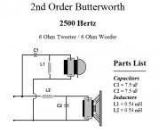 high pass 2nd order.jpg53.4 KB · Views: 529
 -
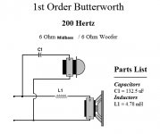 low pass 1st order 200hz.jpg44.3 KB · Views: 566
 -
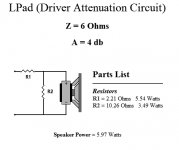 L-pad attenuation circuit.jpg45 KB · Views: 459
 -
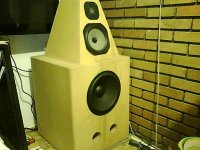 3way speaker pic.jpg93.2 KB · Views: 536
 -
 3way schematic drawing.gif48.9 KB · Views: 1,922
 -
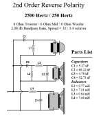 2nd order reverse polarity crossover schem.jpg97.5 KB · Views: 393
your rough draft schematic won't cause any damage to your speakers, but, a couple of questions - where did you get the impedance values from? - these should come from an impedance plot of the driver, at the chosen crossover frequency.
Why did you choose those particular crossover points and slopes? (links to the driver specs & plots might help)
Why did you choose those particular crossover points and slopes? (links to the driver specs & plots might help)
The trouble with passive crossover networks is that you have to level match, and you have to calculate the reactive elements based on what they will see looking out in the rest of the circuit. The "nominal" or rated impedance of a given driver is rarely what you'll have at the frequency you want to do the crossover at. On an 8 ohm driver, it's often more like 15 ohms at 2kHZ, for example. My personal experience trusting published impedance curves has not been very good, but may be better than using the nominal rating. You can measure them, or if you don't have the equipment to do that properly, a good way to get it right is to use a calibrated mic and a pinknoise signal source to see the response of each driver independently. Start with calculated values, and tweak to get it where you want it. This is much easier to do this with a simple one pole (6dB/oct.) circuit. The more complex the circuit (2 pole, etc.), the harder it is to calibrate it. This is why many (including myself) have gone to active crossover circuits with separate poweramps for each driver. With the active approach, it's easy to make it VERY accurate, and with 4 pole cutoff rates. If you had the woofer in a closed box, you could also add low end active EQ, to make the woofer acoustically flat to 20 or 30 HZ (which I do and I love it!). Using active EQ on a ported woofer is not recommended.
My latest speaker is a 3 way, with a 4 pole active crossover at 150HZ, and a one pole passive crossover at 7kHZ. If you're above about 6kHZ, the damage done by a passive crossover is less noticeable.
One other point; if you set the crossover point near where the driver naturally rolls off, this natural rolloff will introduce phase shift, which will add to the phase shift in the crossover electronics. In the end, you might get a flatter frequency response when you reverse the phase of one or more drivers, relative to the driver that is adjacent to it in frequency. Hope this helps.
Last edited:
No point in reinventing the wheel. It would do you no harm to study some existing designs. This three way by Visaton called the Stralet is much the same as what you are trying to do.
Sim it in Boxsim and adjust your acoustic centre depth (point of sound origin) to get the drivers aligned as in your cabinet. I'd look up some Visaton drivers of similar dimension and voice-coil inductance to get an idea of how it will all work and possible changes. The optimise button usually does a good job.
FWIW, the bigger midrange capacitor usually goes at the INPUT to the filter. Keeps the load tidier.
Hi,
If you can't measure, model and stay well away
from x/o calculators. See the FRD tools guide.
rgds, sreten.
http://sites.google.com/site/undefinition/diy (see if nothing else, the excellent FAQs)
http://techtalk.parts-express.com/sh...d.php?t=219617
Zaph|Audio
Zaph|Audio - ZA5 Speaker Designs with ZA14W08 woofer and Vifa DQ25SC16-04 tweeter
FRD Consortium tools guide
http://web.archive.org/web/200909021...esigningXO.htm
RJB Audio Projects
http://web.archive.org/web/200909022...ve99/Spkrbldg/
Speaker Design Works
http://www.htguide.com/forum/showthread.php4?t=28655
A Speaker project
http://www.troelsgravesen.dk/Diy_Lou...r_Projects.htm
Humble Homemade Hifi
Quarter Wavelength Loudspeaker Design
The Frugal-Horns Site -- High Performance, Low Cost DIY Horn Designs
Linkwitz Lab - Loudspeaker Design
Music and Design
Great free SPICE Emulator : http://focus.ti.com/docs/toolsw/fold...t/tina-ti.html
Last edited:
Oh, one other thing. Visaton do some standard crossovers for well-behaved drivers in typical boxes. A choice of crossover frequencies and doubtless you would need some wirewound resistors for attenuation to get the levels right. But not a bad start for your simming.
Crossovers
For all that, some drivers play together nicely, and some are stinkers...
Crossovers
For all that, some drivers play together nicely, and some are stinkers...
You cannot build good speakers without measurements.... designing a new crossover for a pair of homemade 3way speakers....
You cannot build good speakers without measurements.
and maybe not even with that
Hi,
I have a concrete proposal for your crossover problem:


I made the simulation using the 4 ohm version of the woofer. I hope that's the one you have. Note that the driver is not really suited for a vented box. Therefore I highly recommend to seal the vents, you will get a much better bass! The simulation assumes a closed box and a microphone distance of 2 meters.
I have a concrete proposal for your crossover problem:
I made the simulation using the 4 ohm version of the woofer. I hope that's the one you have. Note that the driver is not really suited for a vented box. Therefore I highly recommend to seal the vents, you will get a much better bass! The simulation assumes a closed box and a microphone distance of 2 meters.
Hi, There is something wrong in this sim, I use actual measurements to sim your proposal, I have a low z nearly 2ohms at 100Hz ! the problem is the 150uF
The sensitivity 84dB is too low, Keep it at least at 87dB. This speaker will be near a wall. The bass step with this drivers is less than 6dB, ~3dB
The phase tracking is bad ..
Can you redesign it ?
The sensitivity 84dB is too low, Keep it at least at 87dB. This speaker will be near a wall. The bass step with this drivers is less than 6dB, ~3dB
The phase tracking is bad ..
Can you redesign it ?
Hi,
I have a concrete proposal for your crossover problem:
View attachment 313075
View attachment 313076
I made the simulation using the 4 ohm version of the woofer. I hope that's the one you have. Note that the driver is not really suited for a vented box. Therefore I highly recommend to seal the vents, you will get a much better bass! The simulation assumes a closed box and a microphone distance of 2 meters.
Hello,
The topology of this schematics is good but i see some improvements
1. Reverse the polarity of the tweeter
2. On the mid increase L2 to 1mH and add 10 ohms in series with C2
Have fun.
Oups, only the polarity of the midrange 4V813 needs to be reversed
Keep the woofer and tweeter with the same polarity.right on! thanks for all the responses! so if the nominal impedance isn't what is used to pick the crossover point, how is it decided? i'd much rather base it around 8ohms if can. also, can't find specs for focal 8v413, even contacted focal, and they don't have them anymore! they said its the same as 8v412 model, but can't find spec sheet with any charts or graphed response. i've compiled the three specs into one wordpad page for easier reference.
basically, i'm not to picky, i'm mainly wanting good slightly forward midbass that aren't recessed or muddy and pronounced low bass response that has a tighter attack/decay without bloated sustain/release (not sure if terminology is correct,just trying for an example). i think that a closed box would achieve this better, but am trying to avoid building new boxes.
i play experimental acid jazz/IDM/drum n bass/ambient/abstract/electronic dance music using mostly analog synths/sequencers/drum machine with some acoustic percussion thrown in sometimes. so my main focus is to play my music thru them so using for home theater isn't my objective.
can i use a Moog Voyager to test the specs for the speakers? it has a variable 1-4 pole 24/dB lowpass/bandpass filter that spans 20Hz-12kHz, plus 3 oscillators that span 8 1/2 octaves with tunable frequency control that dips below 20Hz -. it has a noise generator but its hybrid pink/white noise. i also have a separate resonant bandpass filter that is tunable from 110Hz - 1.8kHz.
have looked into using Speakerworkshop to test the speakers, but not wanting to do more work than have to in order to get good sound out of these.
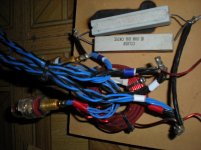
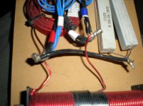
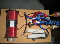
i didn't mention that there is a crossover he designed already hooked up to them, but i don't trust it enough to continue using it even if i'm barely sending any power into them. i've looked at every x-over design i can find, and there is nothing even remotely similar, other than i think he's got somekind of zobel circuit in it. but it doesn't have any capacitors! its composed of
1 Steel Laminate 5.5 mH 15 AWG Inductor rated at .257 DCR ohms
1 Madisound 0.15 mH 19 AWG Air Core Inductor .10 DCR ohms 100 watts
2 15 ohm, 25 watt, Cement Type Wirewound Resistor, 5mm Ø Ceramic Core, Perfect Winding, Solder plated copper leads,
1 thats 10% Tolerance
1 thats 5% Tolerance
I labeled which wires he has going to which drivers using red white and blue
red:tweeters
white:mids
blue:woofer
i then have the output polarity phases as:
redositive
white:negative
not sure if this is standard but matched according to the crossover wires blue/black positive/negative
My friend that designed these speakers and x-overs works for a renowned speaker wire company called Kimber-Kable, but these were his first speakers, which he made back in '98.unfortunately i've not been able to find him in years. otherwise, i would be asking for his help instead.
one more thing, if i was to go the active x-over route, would a 2 channel amp (crown ce2000) suffice, or would i need a separate amp per driver?
thanks and thanks again, i'm very grateful for this forum! keep it real....
basically, i'm not to picky, i'm mainly wanting good slightly forward midbass that aren't recessed or muddy and pronounced low bass response that has a tighter attack/decay without bloated sustain/release (not sure if terminology is correct,just trying for an example). i think that a closed box would achieve this better, but am trying to avoid building new boxes.
i play experimental acid jazz/IDM/drum n bass/ambient/abstract/electronic dance music using mostly analog synths/sequencers/drum machine with some acoustic percussion thrown in sometimes. so my main focus is to play my music thru them so using for home theater isn't my objective.
can i use a Moog Voyager to test the specs for the speakers? it has a variable 1-4 pole 24/dB lowpass/bandpass filter that spans 20Hz-12kHz, plus 3 oscillators that span 8 1/2 octaves with tunable frequency control that dips below 20Hz -. it has a noise generator but its hybrid pink/white noise. i also have a separate resonant bandpass filter that is tunable from 110Hz - 1.8kHz.
have looked into using Speakerworkshop to test the speakers, but not wanting to do more work than have to in order to get good sound out of these.
i didn't mention that there is a crossover he designed already hooked up to them, but i don't trust it enough to continue using it even if i'm barely sending any power into them. i've looked at every x-over design i can find, and there is nothing even remotely similar, other than i think he's got somekind of zobel circuit in it. but it doesn't have any capacitors! its composed of
1 Steel Laminate 5.5 mH 15 AWG Inductor rated at .257 DCR ohms
1 Madisound 0.15 mH 19 AWG Air Core Inductor .10 DCR ohms 100 watts
2 15 ohm, 25 watt, Cement Type Wirewound Resistor, 5mm Ø Ceramic Core, Perfect Winding, Solder plated copper leads,
1 thats 10% Tolerance
1 thats 5% Tolerance
I labeled which wires he has going to which drivers using red white and blue
red:tweeters
white:mids
blue:woofer
i then have the output polarity phases as:
red
ositivewhite:negative
not sure if this is standard but matched according to the crossover wires blue/black positive/negative
My friend that designed these speakers and x-overs works for a renowned speaker wire company called Kimber-Kable, but these were his first speakers, which he made back in '98.unfortunately i've not been able to find him in years. otherwise, i would be asking for his help instead.
one more thing, if i was to go the active x-over route, would a 2 channel amp (crown ce2000) suffice, or would i need a separate amp per driver?
thanks and thanks again, i'm very grateful for this forum! keep it real....
Attachments
8V412 : http://lephenixnoir.net/images/pdfs/8v412.pdf
TC120TD : http://www.diyparadiso.com/datasheets/speaker/focal/TC120TD5.pdf
Let us know how things go.
TC120TD : http://www.diyparadiso.com/datasheets/speaker/focal/TC120TD5.pdf
Let us know how things go.
Last edited:
- Status
- This old topic is closed. If you want to reopen this topic, contact a moderator using the "Report Post" button.
- Home
- Loudspeakers
- Multi-Way
- 3 way crossover help