Hi everybody
I m trying to learn how to design a loudspeaker so if you see some dumb newbie questions I m sorry for that .
I picked 2 drivers to begin with :
Woofer : Scanspeak P17WJ-00-008
Tweeter : Scanspeak D2905/930000
then I ran Speaker Builder pro to calculate internal volume for woofer and I ended up with a vented box with volume of 22.8 liter and one 9cm long and 5cm diameter port for fb of 45hz . (I didn't go for a custom volume ,just went with suggested volume for maximum flatness)
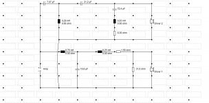
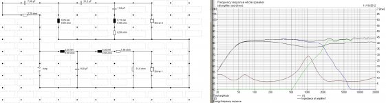
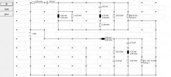
then I desiged a 3rd order butterworth crossover at 2500hz as suggested and lPad for woofer and series notch filter for tweeter @ 650hz as it is the fs of tweeter
(I attached crossover circuit)
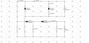
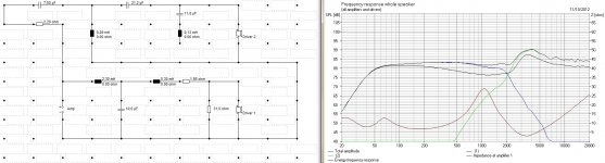
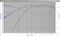
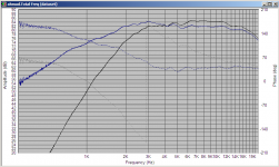
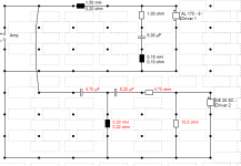
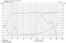
but when I ran simulation in Boxsim I have a big spark around 4000 hz (Image attached) so I changed the series notch filter to 4000hz and the spark is gone (crossover circuit attached) but I have a another small spark around 2500hz now(Image attached) .
so where did I go wrong ? or is it as good as it gets ? can I add BSC to solve it or it s not because of that because as I change the placment of drivers it doesn't change that much ,...
thanks in advance")
I m trying to learn how to design a loudspeaker so if you see some dumb newbie questions I m sorry for that .
I picked 2 drivers to begin with :
Woofer : Scanspeak P17WJ-00-008
Tweeter : Scanspeak D2905/930000
then I ran Speaker Builder pro to calculate internal volume for woofer and I ended up with a vented box with volume of 22.8 liter and one 9cm long and 5cm diameter port for fb of 45hz . (I didn't go for a custom volume ,just went with suggested volume for maximum flatness)
then I desiged a 3rd order butterworth crossover at 2500hz as suggested and lPad for woofer and series notch filter for tweeter @ 650hz as it is the fs of tweeter
(I attached crossover circuit)
but when I ran simulation in Boxsim I have a big spark around 4000 hz (Image attached) so I changed the series notch filter to 4000hz and the spark is gone (crossover circuit attached) but I have a another small spark around 2500hz now(Image attached) .
so where did I go wrong ? or is it as good as it gets ? can I add BSC to solve it or it s not because of that because as I change the placment of drivers it doesn't change that much ,...
thanks in advance
Attachments

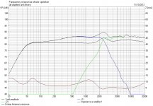
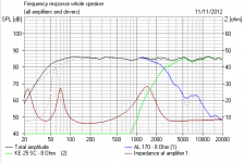
Without the raw driver responses on that graph, it would be hard to give advice. Did you measure the speakers or trace the published graphs, or what? Are the real driver impedance plots loaded? Anyway, I can say a couple things:
1. watch your impedance, you're hitting ~2Ω on that first plot
2. The hump at 2500Hz is just the drivers summing. Start the rolloff sooner on one or the other, and it will go away, although if phase isn't being included correctly, the sim won't be accurate there anyway.
3. You seem to have a rising response to about +6dB in the treble - do you want that?
Ahmad, my friend, you are going seriously wrong in applying that 650Hz LCR Fs impedance correction filter to the tweeter. You simply don't need it here. Changing it to 4kHz is just making it worse. Lose it altogether. You are getting out of your depth.
Very nice Vifa P17WJ-00-08 Polycone Woofer. And the Scanspeak Classic D2905/9300 Tweeter looks OK too.
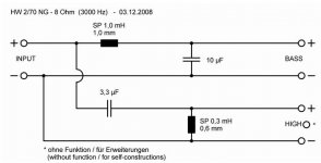
I would try this simple Visaton 3kHz Filter for a bookshelf. Add a 10W wirewound resistor around 2.2R or 3.3R to the tweeter input filter if the treble is too bright.
Naturally we could do better. Read Lynn Olson for deeper thoughts. But bear in mind Lynn is using an effectively 4 ohm bass setup.
Very nice Vifa P17WJ-00-08 Polycone Woofer. And the Scanspeak Classic D2905/9300 Tweeter looks OK too.
I would try this simple Visaton 3kHz Filter for a bookshelf. Add a 10W wirewound resistor around 2.2R or 3.3R to the tweeter input filter if the treble is too bright.
Naturally we could do better. Read Lynn Olson for deeper thoughts. But bear in mind Lynn is using an effectively 4 ohm bass setup.
Attachments
thanks dumptruck and steve . I didn't import anything (raw driver responses ,real driver impedance plots , ...) I know it s hard and almost impossible to have a accurate answer without them but it doesn't matter because i don want to build this speaker ,i m just trying to learn and understand crossovers and how speakers behave . and another thing is I donno how to import driver's raw graphs and plots into boxsim yet , I could easily go with a already added visaton driver but I wanted to learn how to work with other drivers as well .
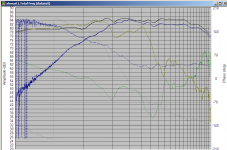
anyway thanks again for your tips , I changed L2 from 0.75 to 2.3 mh and L3 from 0.25 to 30 mh and I got rid of mid low 3db boost and added 2.2ohm before the tweeter crossover and I got a almost flat respond from it (the 2500hz spark still exist but it s smaller) then I removed snf as steve said but I got a very big spark arond 3.5k to 4k , so I reattached it again , so am I good now ???
why is it wrong ? as you see i removed it and i have that peak around 3.5k-4k , maybe I can get rid of that without snf and with changing the rolloff poit ?
what EASY to useD) software for simulating drivers and box and crossovers you guys suggest ?
, I could easily go with a already added visaton driver but I wanted to learn how to work with other drivers as well . anyway thanks again for your tips , I changed L2 from 0.75 to 2.3 mh and L3 from 0.25 to 30 mh and I got rid of mid low 3db boost and added 2.2ohm before the tweeter crossover and I got a almost flat respond from it (the 2500hz spark still exist but it s smaller) then I removed snf as steve said but I got a very big spark arond 3.5k to 4k , so I reattached it again , so am I good now ???
you are going seriously wrong in applying that 650Hz LCR Fs impedance correction filter to the tweeter. You simply don't need it here. Changing it to 4kHz is just making it worse. Lose it altogether.
why is it wrong ? as you see i removed it and i have that peak around 3.5k-4k , maybe I can get rid of that without snf and with changing the rolloff poit ?
what EASY to use
D) software for simulating drivers and box and crossovers you guys suggest ?Attachments
thanks dumptruck and steve . I didn't import anything (raw driver responses ,real driver impedance plots , ...) I know it s hard and almost impossible to have a accurate answer without them but it doesn't matter because i don want to build this speaker ,i m just trying to learn and understand crossovers and how speakers behave . and another thing is I donno how to import driver's raw graphs and plots into boxsim yet :
You can use SPL copy for FRD/ZMA files
Unless there's something wrong with the response you're using, that peak is something you are causing, not something to get rid off. That's why you don't need the LCR. You're probably ending up with too high of Q. Go to the last tab "frequency response electrical". Does the HF curve look crazy? You can figure this out yourself. Start changing the values of the HF components (just a basic topology, no LCR) and watching what happens.
thanks as I said i didn't import any raw driver responses ,real driver impedance plots , ... and it seems that boxsim assume it as flat , I don want it to give me accurate results i just want to learn crossover and speaker behavior ... i will start to change values and maybe drivers and I ll let you know
well if you were using ruler flat FR's then something is going very wrong with the modeling!
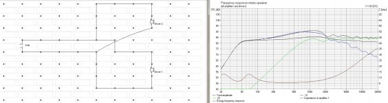
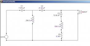
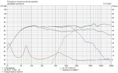
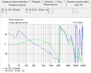
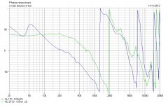
I just put your first circuit into speaker workshop with my DMS37 tweeter FR and Impedance (real in box measurements) and I see NO peaking at all. The only thing that is off is that speaker workshop is boosting the higher frequencies by around 2db (which I see every now and then and I think is a bug).
FR plots below. Blue is original raw response. Black is with your filter. Second image is with black adjusted to reflect reality (with respect to the levels).
I didn't model the bass part of the circuit, so I guess it might be interacting...
edit: ok I added my MW144's (with impedance double to nominally 8 ohms) and put in the bass part of the circuit as well. Note that the tweeter response is 2db higher than what it would be in real life. Surprisingly good all things considered, and NO peaking... all inductors were modeled with zero series resistance as per the OP, but realistically they should have at least 0.1ohms.
Tony.
Attachments
Last edited:
ok , first of all thanks everybody for your help ...
after a bad start i start over with 2 included drivers in boxsim
visaton al170 and ke25sc as tweeter .
I chose crossover point for 2000hz and start with it , after i put my calculations in sw and after adding some filters anywhere i saw a peakD) here s the results , what do you think ? and how it can go simpler and better and why ..
thanks in advance
edit : there s a peak around 6200 that s annoying me , i know it s the tweeter respond but can i get rid of it ?
again thanks all
after a bad start i start over with 2 included drivers in boxsim
visaton al170 and ke25sc as tweeter .
I chose crossover point for 2000hz and start with it , after i put my calculations in sw and after adding some filters anywhere i saw a peak
D) here s the results , what do you think ? and how it can go simpler and better and why ..thanks in advance
edit : there s a peak around 6200 that s annoying me , i know it s the tweeter respond but can i get rid of it ?
again thanks all
Attachments
Last edited:
You're getting the hang of it, Ahmad. The amazing "optimise" button helps too!
I got something not a million miles away. 20L cabinet. Of course, I lost the stupid LCR filter on the tweeter. It has one built in, as it goes. Just the 6kHz bass notch needed. Give you a tip. Take out the resistor on the bass notch to see where it hits.
Your crossover is a bit low, IMO. But that particular tweeter might get away with it. Keep an eye on phase, and try to get the impedance as high as possible. It makes life easier for the amp.
Attachments
You're getting the hang of it, Ahmad. The amazing "optimise" button helps too!
I got something not a million miles away. 20L cabinet. Of course, I lost the stupid LCR filter on the tweeter. It has one built in, as it goes. Just the 6kHz bass notch needed. Give you a tip. Take out the resistor on the bass notch to see where it hits.
Your crossover is a bit low, IMO. But that particular tweeter might get away with it. Keep an eye on phase, and try to get the impedance as high as possible. It makes life easier for the amp.
mmm , very interesting , i know it ll sound stupid but i didn't think of a third order crossover for tweeter ... lemme redo all that again
i agree with Steve, 2khz is too low for the KE20.
In my tower I found the G20SC and KE20 almost interchangable. The G20SC is actually flatter in my design so the option for the KE got shelved.
I used 5uF and 0.33mH for 2nd order, L pad on the driver side.
A small tip. I always add an R to every component, in series, sometimes in parallel or T filter configuration. As steve says the 'Optimise' button is useful, as long as you optimise a couple of components at a time. The extra Rs I add can either stay or are removed depending on if theyre worthwhile.
Last edited:
i tried to tweak it for a while and that was my best result (until steve showed me the bright light ) it s my very first try and even that i m trying to tweak i don know exactly what i m doing have to spend a lot of time on it , have to learn it gonna build some studio monitor for my self one day
) it s my very first try and even that i m trying to tweak i don know exactly what i m doing have to spend a lot of time on it , have to learn it gonna build some studio monitor for my self one day I suggest the component values in my last post as a starting point for the KE20. Once you get into using your own .frd and .zma data for the drivers you're actually going to use then things really get far more interesting
Also, some peaking may be present due to the baffle diffraction. Id recommend experimenting with offsetting the tweeter from the centreline of the baffle. Just 1cm can make all the difference. Height and inter-driver spacing has similar effects.
Also, some peaking may be present due to the baffle diffraction. Id recommend experimenting with offsetting the tweeter from the centreline of the baffle. Just 1cm can make all the difference. Height and inter-driver spacing has similar effects.
Last edited:
thanks mondogenerator i sure will test ur suggestions and i m tweaking with different baffle setting as well .
i tried something different this time , instead of passive crossover i tried active filters and with a 24db lpf at 2200 with q of 0.4 and a 12db hpf at 2200 and with q of 0.8 , i got the results as you see , but when the phase respond looks wierd , is it me or i m doin somethin wrong ??!
edit : is there any way to get rid of that annoying 5200 peak ??
Attachments
Last edited:
- Status
- This old topic is closed. If you want to reopen this topic, contact a moderator using the "Report Post" button.
- Home
- Loudspeakers
- Multi-Way
- NEWBIE Need help with a two way design ...