it looks like that peak is either due to the woofer breakup peak, OR the baffle placement of the tweeter.
Thats all i can think of, UNLESS the slope of the HP is 'doglegged' with a 1st order slope between the 2nd pole and 5khz.
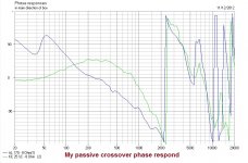
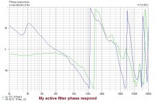
the peak is because of the woofer breakup peak , in passive crossover we coud get rid of it with a series notch filter but i donno how to get rid of it now with active filters , what bout phase responds ? is that ok ?
mmm , very interesting , i know it ll sound stupid but i didn't think of a third order crossover for tweeter ... lemme redo all that again
I tried to post this earlier but my 3G connection on the train dropper out
Hi Ahmad, not sure if you know this or not, but you should be aiming for a particular acoustic rollof. say for example 4th order Linkwitz riley, To get that the best may be a third order network.
I suspect your software will have a target function. You put in what target response you want and it shows that on your graph, you then tweak your crossover until it as closely matches that target response as you can get. It is the final accoustic response that matters, not how you get there electrically
Other things to be aware of are the phase tracking of the tweeter and woofer. small tweaks to the crossover can bring them closer or further apart without affecting the FR much. The closer they track through the crossover region the better.
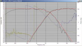
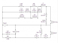
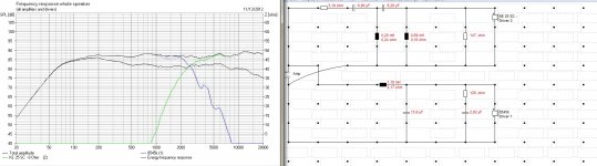
I've attached an image of my crossover to show you what I am talking about. Black traces are the filtered woofer and tweeter response. Red are the target 4th order bessel at 2.8Khz Blue trace is woofers phase, green trace is tweeters phase.
Electrically the tweeter is 3rd order, woofer is electrically second order with two notch filters.
Tony.
Attachments
thnx Tony for your respond , I m still learning that software i donno if it has a function to give it a target respond but i ll look into it , u mentioned that acoustic respond is important , boxsim shows something call acoustic power respond is that what you mean ? and if that s what you mean it is the real world respond that i should hear from speaker , am i right ? if that s so , it s far from the freq respond that crossover makes , what should i do to make them as close as possible , and if i m wrong please explain what that meansI suspect your software will have a target function. You put in what target response you want and it shows that on your graph, you then tweak your crossover until it as closely matches that target response as you can get. It is the final accoustic response that matters, not how you get there electrically
about the phase , i m not familiar with phase respond yet , in previous posts there are 2 phase responds , one steve posts that s similar to my passive crossover and other one that i posted from my active filter , they r different and if steve's phase respond is right so the second one is wrong and i should do somethin about that ??? and if yes what should I do ?
Power response is not something I have much experience with, however I believe that it is representative of the total power emitted by the speaker (in all directions, horizontal and vertical) as opposed to the Frequency response which is measured (usually on axis) at a particular point. The reason it is also important is that the sound that reaches you at the listening position is a combination of the direct sound and also of reflections. If your speaker is uniform in it's power response then your brain should not get confused by the reflections. If it is very uneven in certain ways then your brain may not be able to make sense of the information.
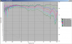
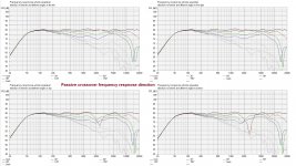
The acoustic response I was referring to is the on axis Frequency response. It is also good to look at the behaviour off axis as well say at 15 deg, 30 deg and 45 deg to make sure that there isn't anything odd happening in those off axis areas. Ideally the curves should follow one another with the only difference being that the speaker becomes more and more directional (frequency response starts to drop off at lower and lower frequencies) as the off axis angle increases.
Attachment is actual measurement of my MTM at angles from on axis through 90 deg off axis, which shows how the frequency response varies as the off axis angle increases.
I'll have to look again at Steve's and your active posts.
The way I think about phase is to thing at what point on a sine wave is the signal. If you have two speakers producing a sine wave at the same frequency then if both are at the same point on the sine wave at the same time then they are in phase. If they are in phase they add together. If they are exactly 180 degrees out of phase they cancel each other out. At 90degress diference they have no effect on each other.
The below picture found though google images (from this site: http://finalequinox.com/viewtopic.php?f=17&t=4695 ) will help with understanding phase (note that I just thought the image is clear, I'm not advocating anything else on the site)
Tony.
The acoustic response I was referring to is the on axis Frequency response. It is also good to look at the behaviour off axis as well say at 15 deg, 30 deg and 45 deg to make sure that there isn't anything odd happening in those off axis areas. Ideally the curves should follow one another with the only difference being that the speaker becomes more and more directional (frequency response starts to drop off at lower and lower frequencies) as the off axis angle increases.
Attachment is actual measurement of my MTM at angles from on axis through 90 deg off axis, which shows how the frequency response varies as the off axis angle increases.
I'll have to look again at Steve's and your active posts.
The way I think about phase is to thing at what point on a sine wave is the signal. If you have two speakers producing a sine wave at the same frequency then if both are at the same point on the sine wave at the same time then they are in phase. If they are in phase they add together. If they are exactly 180 degrees out of phase they cancel each other out. At 90degress diference they have no effect on each other.
The below picture found though google images (from this site: http://finalequinox.com/viewtopic.php?f=17&t=4695 ) will help with understanding phase (note that I just thought the image is clear, I'm not advocating anything else on the site
) An externally hosted image should be here but it was not working when we last tested it.
Tony.
Attachments
first of all thanks tony for your patience and detailed answers
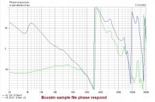
i know about phase , i m mixing music so I have to deal with phase sometimes , I didn't get you the first time , the thing is I donno what these charts means , first image is the phase respond from boxsim sample file , second one is the phase respond of my passive crossover ,these two are close enough but the third image is phase respond from my active filter and i donno if it s ok or not cuz it looks different ,
and about the acoustic respond as i mentioned I m mixing music and my goal is to learn loudspeaker designing to build my own monitors one day (as they are so over priced IMO and building one doesn't seems impossible) and as you know nearfield monitors used mostly as on axis and in acoustic treated rooms , so off axis responds doesn't bother me that much , but learning to handle it is a MUST ofcours
Attachments
Last edited:
hi again .
i tried to make a frd file for scanspeak 18w8545k and import it into boxsim ,(still no zma)
any way I tried to make a crossover for that with ke25 and here s the results ,
is it any good ?
i didn't get any good results until i tried 4th order bessel for tweeter
i tried to make a frd file for scanspeak 18w8545k and import it into boxsim ,(still no zma)
any way I tried to make a crossover for that with ke25 and here s the results ,
is it any good ?
i didn't get any good results until i tried 4th order bessel for tweeter
Attachments
Last edited:
- Status
- This old topic is closed. If you want to reopen this topic, contact a moderator using the "Report Post" button.