Oh, that's what the speaker looks like to the amplifier - that's definitely the electrical or impedance phase angle. Speakers almost never look purely resistive to an amplifier - the impedance, boththe "8 ohms" approximation of the absolute value and the phase angle between the voltage and the current, change with frequency, and can be either inductive or capacitive in different frequency ranges (though I think most of the range is inductive). Resistive is the easiest for the amplifier to drive. The more reactive (inductive or capacitive) the speaker is, the more current the amplifier must provide to get the same output as a frequency where the speaker's impedances is more (nearly) resistive .
Expect Smith-chart-type graphs to be posted...
Expect Smith-chart-type graphs to be posted...
Hi,
Difficulty to drive is related to the impedance phase angle,
and nothing to do with high order x/o acoustic phase changes.
Simply put you want to avoid large phase angles at the same time
as low impedance, large phase angles at high impedance don't matter.
For a purely resistive 8 ohm load power is dissipated in the load.
For a purely reactive 8 ohm load at the same current no power is
dissipated in the load and this power is dissipated by the amplifer.
The more reactive a given load impedance, the more it thermally
stresses the amplifier compare to a purely resistive load. As the
thermal stress on amplifier into resistive loads depends on
current there are some simple rules of thumb :
An amplifier for 8 ohm speakers must be able to drive 4R.
An amplifier for 6 ohm speakers must be able to drive 3R.
An amplifier for 4 ohm speakers must be able to drive 2R.
In all cases for the latter not necessarily continuously. This
covers the phase / reactance issues of nearly all speakers.
With proper amplifier design and sensible speaker design its no
big deal most of the time. However with chip-amps and their
aggressive protection and in particular current limiting, and
their specification chasing, supply design is a big issue.
rgds, sreten.
Last edited:
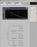
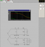
No, those diagram show the phases generated by the crossover, or more accurately, the difference between the phase of the input voltage (of the crossover) and the phases of the output voltages at the driver terminals. These determine whether each driver should be connected with "+" polarity or "-" polarity to get the proper acoustic phase from the speaker. These have little to do with the phase between the input's voltage and current. That phase also varies with frequency, whether it's a single full-range driver or a multi-way system with a crossover. One design isn't necessarily harder than another for an amplifier to drive, but specific models of speakers are harder than others.
The whole thing is basically AC circuits analysis (one of the fundamental courses in Electrical Engineering), which needs (the mathematical concept of) complex numbers as a prerequisite.
The whole thing is basically AC circuits analysis (one of the fundamental courses in Electrical Engineering), which needs (the mathematical concept of) complex numbers as a prerequisite.
OK, that being said, how can you predict the Impedance and Acoustic "Phase" of a given loudspeaker in simulation?
I take it Crossover Pro 3 cannot show these aspects of design?
You answered your own question there...
Basically, the phase plot is the derivative (calculus) of the FR plot. You can extract phase with a Hibert-Bode transform applet, but that doesn't mean you can use it in a certain program to your advantage. Some simple calculators or simulators assume perfect resistive loads and flat-FR drivers; and offsets, phase, and such are not factored into the box of tools to produce good results.
Later,
Wolf
- Status
- This old topic is closed. If you want to reopen this topic, contact a moderator using the "Report Post" button.
- Home
- Loudspeakers
- Multi-Way
- What's The Deal With Phase Angle?