: ) torgeirs come on, seems you generalize so we can't build anything speaker stuff anymore and have fun, go tell KEF or Danley their short spacing solutions wont work good with slopes more than 1st or 2nd order.
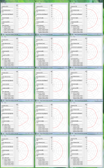
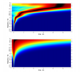
Sorry below vertical power responses is own simulations and not prepared to be easy to read for others but if you look at it info is XO point is at 80Hz (the one at left column in middle) then first four is within 1/4 wave length at XO point and fifth one is within 1/8 wave length and slopes are 1=LR2 2=LR4 3=LR8 4/5=LR16, think spacing distances are relative short so most real builds will be worse. If you direct compare the first four notice the one you recommend have worst and widest error, the steeper ones get less and less error except right at XO frq because they get faster over XO region, and fifth one being very steep and very short spaced is almost perfect as a one point source. Almost forgot tell configuration is WT in simulations and change it to WTW results will look different.
Sorry below vertical power responses is own simulations and not prepared to be easy to read for others but if you look at it info is XO point is at 80Hz (the one at left column in middle) then first four is within 1/4 wave length at XO point and fifth one is within 1/8 wave length and slopes are 1=LR2 2=LR4 3=LR8 4/5=LR16, think spacing distances are relative short so most real builds will be worse. If you direct compare the first four notice the one you recommend have worst and widest error, the steeper ones get less and less error except right at XO frq because they get faster over XO region, and fifth one being very steep and very short spaced is almost perfect as a one point source. Almost forgot tell configuration is WT in simulations and change it to WTW results will look different.
Attachments

Last edited:
")
The problems with LR filters is of course where distance between drivers is comparable to wavelength of crossover frequency. As the low freq driver starts to beam of axis the LR requirements are not met any more. That is > 1000 hz or sub - satelite
At > 1000 hz the group delay requirements of the ear is quite tight.
Another point that Linkwitz makes himself of moreway filters >3 is that they can not be parallell as the phase of the filters will interact and LR is no longer possible.
So it must be a cascade of 2 way filters. Not all popular "DSP boxes" support this.
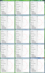
Yes thanks torgeirs saw the more than three-way LR filter problem pages back when pos pointed it out and linked to it, from that time started include all other side drivers low or high pass function into acoustic target slopes because even for two way if one pass band is narrow it will make small difference. Below is example that two-way can have small error summing 15Hz (BW2) - 80Hz (LR4) band pass with 80Hz (LR4) - 20kHz (BW2) bandpass, purple summing response show the small error and orange summing is the right one. Difference is planned system stop bands 15Hz and 20kHz is cascaded to XO point for orange sum, for this example difference in right or wrong for amplitude slope is down very deep but phase tracking show why as seen in picture two where phase is not absolute coherent as in the right one at picture three.
Great man you really have a technically setup there and much setup points to keep track off, can imagine Jimi's notes will tell great story thru such system enjoy and have fun.
Speaking of fun. My fun system is:
< 70 hz: 4 x 12" + 2 x 15" peerless/scan speak + slaves
< 160 hz: 15" audax
< 600 hz: 10" seas
< 2500hz: 6" seas
> 2500hz: vifa ringradiator
All 48dB/oct and heavy EQ
Jimi is playing for me as it was meant to be. And yes it is fun!
Great man you really have a technically setup there and much setup points to keep track off, can imagine Jimi's notes will tell great story thru such system enjoy and have fun.
Attachments
The problems with LR filters is of course where distance between drivers is comparable to wavelength of crossover frequency. As the low freq driver starts to beam of axis the LR requirements are not met any more. That is > 1000 hz or sub - satelite
At > 1000 hz the group delay requirements of the ear is quite tight.
Another point that Linkwitz makes himself of moreway filters >3 is that they can not be parallell as the phase of the filters will interact and LR is no longer possible.
So it must be a cascade of 2 way filters. Not all popular "DSP boxes" support this.
You were arguing against the use of steep filters and now we are talking about devises that can use such slopes.
BYRTT clearly showed us: it depends...
As with anything, really...
We are on the RePhase thread, giving us more power to actually get the slopes we want or need, acoustically.
You were arguing against the use of steep filters and now we are talking about devises that can use such slopes.
Everything is constantly moving in world of relativity.
Last edited:
Yes, rephase is a very powerful tool so it is useful to be aware of the side effects of steep filtering.
To believe two speaker elements can be joined according to LR acoustically inside a normal room and at 80 hz is futile.
The two drivers will not have constant phase difference over anywhere near the required bandwith and 45 degree vertical offaxis area.
But guess people just call it LR anyway and chooses the requirements that suits them
Hmmm maybe 80Hz point comes from my examples in post 2101 / 2105, keep in mind they are nothing but examples so keeping other dependencies relative same one can virtual transfer them to other frq points in they will look same there then, except not taking into count that acoustic XO points say below 500Hz in real world rooms are most probably more difficult and time consuming task to get right than frq above 500Hz. Own experience is LR slopes don't need to be a big compromise but can be a solution although with dependencies, is bit surprised subject keep coming up especially because torgeirs lately said his own LR solution play sound for him as it was meant to be.
With the SPLs I use to play Jimi as it was meant to be the ear distorts more than the speakers. And the speakers distorts so little because of sharp filters, eg. low cone displacement without using horns. But there may be some group delay distortion that can be heard at lower SPLs. The group delay distortion is because of 48 dB/oct flilters and drivers that do NOT have constant phase difference inside the filtering bandwith and inside all vertical listening angles (+-45 degrees). The summed phase from two drivers then gives phase variation with frequency that also results in group delay distortion.
The frequencies with to much group delay will depend on where my ears are off axis
Of course it do not sound horrible. It actually sounds very good, but my intelect tells me it is not the best solution for chamber music (that I never listen to)
So in summary the evil side of sharp filters are groupdelay because of noncontant phase difference between the drivers of axis( vertically)
Hi torgeirs, think would take myself forever to calibrate a 5-way system : )
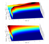
In you have 3060º phase turn distortion inside system stop band sure you will have big group delay, simulated comparison to head phones or chamber music instrument playing live in front of you show quite some difference.
Don't understand about not have constant phase difference inside the filtering bandwidth, difference is the confusing word used because aren't LR supposed to be in phase although a turning one.
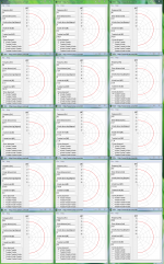
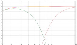
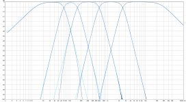
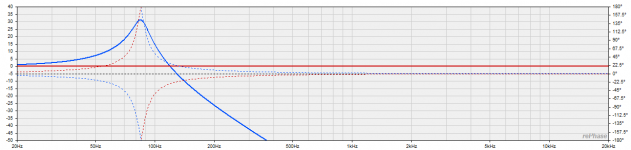
Have you DSP power to time align and using most correct cascaded slopes as target curves shown as dark blue ones below based on 15Hz-25kHz system verse light blue single textbook ones.
In you have 3060º phase turn distortion inside system stop band sure you will have big group delay, simulated comparison to head phones or chamber music instrument playing live in front of you show quite some difference.
Don't understand about not have constant phase difference inside the filtering bandwidth, difference is the confusing word used because aren't LR supposed to be in phase although a turning one.
Have you DSP power to time align and using most correct cascaded slopes as target curves shown as dark blue ones below based on 15Hz-25kHz system verse light blue single textbook ones.
Attachments
Last edited:
Hi again gang!
Heya , I got a bit of a noobish question maybe I can get help with.
I know I'm the guy that tries to be ahead of myself but eventually I catch up.
I've been screwing with REW and rephase now 1.5yrs and I still haven't been able to figure this out and I'm embarrassed to ask but here it goes. (And yes I've searched for the answer and thought I found it but want to be sure because of course it went just a tad bit over my head at times)
So, to refresh I have a Dirac live box in front of 3 2x4HDs. In my car.
I use the HDs for fir crossovers and small corrections a la rephase that Dirac didn't quite get done for me.
Okay on with the questions (nobody cares about my equipment I know already, I was just saying as it relates to the question)
When making filters in rephase across fir channels, does the IR offset figure in windowing truncation?
To further that,
Let's say I do rectangular window on one filter and a hann window on another filter ,
Will the ir offset account for the amount of truncated time across FFt blocks?
Or do I need to use the same window across all channels ?
And 2ndly , does asymmetrical tap allocation effect this in any way across channels in the total ir offset?
If I have a 4 way and each pair has a diffrent FFt size will the ir offset just simply need to be plugged in to delay? How does asymmetrical FFts relate to smearing in the IR across all channels (with or without diffrent types of Windows used)
The total FFt size stayes relatively short no? No longer than the largest one in the mix right?
Do I run any risk of smearing the IR due to freely using rephase across channels in a 4 way?
And lastly , does having a Dirac box in front the the HDs change anything or make it to where I need to do something different, meaning; does the output stream carried by toslink from the Dirac minidsp have any attributes to it that I should know about when adding more fir in series after it?
Or does it output plain old 24/96 like a music file would do coming out of player or a CD player or something?
Many questions,
But
Oh many thanks ��
and much appreciated
Last edited:
Hi torgeirs, think would take myself forever to calibrate a 5-way system : )
In you have 3060º phase turn distortion inside system stop band sure you will have big group delay, simulated comparison to head phones or chamber music instrument playing live in front of you show quite some difference.
Don't understand about not have constant phase difference inside the filtering bandwidth, difference is the confusing word used because aren't LR supposed to be in phase although a turning one.
Have you DSP power to time align and using most correct cascaded slopes as target curves shown as dark blue ones below based on 15Hz-25kHz system verse light blue single textbook ones.
Thank you for visualising the group delay. Actually it is not that far from normal "allowed" group delay vs frequency. But certanly it is not ideal.
You are right about the 0 degree phase difference inside filtering band to be propper LR.
If its not, the lobe will be pointing up or down and the speaker must be tilted to to compensate.
I think It is often forgotten, though, that the differense must be 1)0 degrees and 3) constant through out the filterbandwith.
And if we look at the actual acoustic waves from the speaker elements that
*has different radiation pattern
*has taken slightly different acoustic paths to the ear
*generateds different reflections
the constant/0 phase difference requirement is almost impossible to achieve under 1 m wavelength, and domnestic speaker sizes/placement
Luckily systems can still sound good using LR electical
Attachments
Last edited:
Hi Pos, hi all,
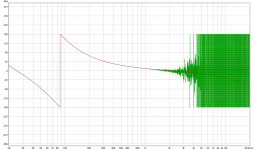
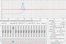
Beginning to play with idea of using all pass filters to help flatten phase on a driver-by-driver basis.
I'm particularly interested in 2nd order inverted all-pass, hopefully accomplished by using rePhase's 'compensate'.
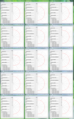
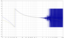
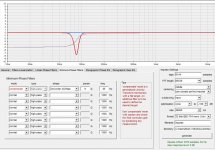
One thing I don't understand yet (among many!) is why I get a magnitude notch like the one below.... my meager understanding of all-pass is that it doesn't effect magnitude ????
(Second screen shows parametric eq to overcome the notch.)
Any help understanding this appreciated
Thx, Mark
Beginning to play with idea of using all pass filters to help flatten phase on a driver-by-driver basis.
I'm particularly interested in 2nd order inverted all-pass, hopefully accomplished by using rePhase's 'compensate'.
One thing I don't understand yet (among many!) is why I get a magnitude notch like the one below.... my meager understanding of all-pass is that it doesn't effect magnitude ????
(Second screen shows parametric eq to overcome the notch.)
Any help understanding this appreciated
Thx, Mark
Attachments
Hi Mark,
As BYRTT suggests 6144 taps is not enough for such an abrupt phase shift at low frequency (ie high group delay).
Your screenshot does not show the degree scale, but this is a rapid 360° phase shift.
(by the way you can use the "save graph screenshot" or "save window screenshot" functionalities in the file menu, and the latter will also anonymise the directory entry for you)
You would get a flatter magnitude response by setting centering to "100%" (peak on the right side of the FIR) and selecting a rectangular windowing.
But are you sure you need this correction?
This kind of phase shift is what you get when chaining two 2nd order filters with Q=6, and this implies more than 30dB of boost at the cutoff frequency:
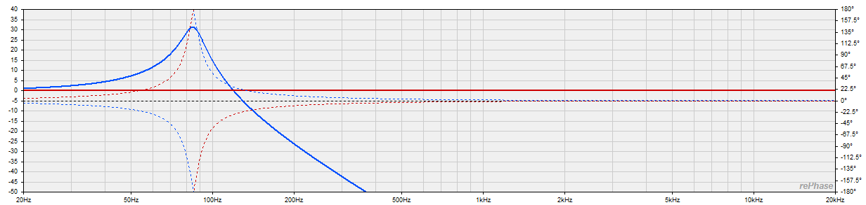
If this happens for real (and is not an artifact of some comb filtering with reflexions in the measurement) then you have more to worry about the magnitude response, and this is better addressed using minimum-phase EQ.
Regarding the principle of using all-pass in reverse mode, this is in essence what the "filter linearization" tab does, but limited to known types (and realistic Q values)
An "LR 24dB/oct" filter linearization is equivalent to a 2nd order all-pass with Q=0.707 in compensate mode.
Hope this helps
As BYRTT suggests 6144 taps is not enough for such an abrupt phase shift at low frequency (ie high group delay).
Your screenshot does not show the degree scale, but this is a rapid 360° phase shift.
(by the way you can use the "save graph screenshot" or "save window screenshot" functionalities in the file menu, and the latter will also anonymise the directory entry for you)
You would get a flatter magnitude response by setting centering to "100%" (peak on the right side of the FIR) and selecting a rectangular windowing.
But are you sure you need this correction?
This kind of phase shift is what you get when chaining two 2nd order filters with Q=6, and this implies more than 30dB of boost at the cutoff frequency:
If this happens for real (and is not an artifact of some comb filtering with reflexions in the measurement) then you have more to worry about the magnitude response, and this is better addressed using minimum-phase EQ.
Regarding the principle of using all-pass in reverse mode, this is in essence what the "filter linearization" tab does, but limited to known types (and realistic Q values
)An "LR 24dB/oct" filter linearization is equivalent to a 2nd order all-pass with Q=0.707 in compensate mode.
Hope this helps
Attachments
Last edited:
Hi Thomas,
You would say 2 2nd order all-pass ?
I'm getting out...

An "LR 24dB/oct" filter linearization is equivalent to a 2nd order all-pass with Q=0.707 in compensate mode.
You would say 2 2nd order all-pass ?
I'm getting out...
Hi Thomas,
You would say 2 2nd order all-pass ?
I'm getting out...
Why ?
- Home
- Design & Build
- Software Tools
- rePhase, a loudspeaker phase linearization, EQ and FIR filtering tool