Hi I'm a bit late to the party but here is a post that I wrote before on calculating notch filters.
The centre frequency is easy and accurate using the formula in my experience, getting the Q right is another matter!! Also don't be surprised if the notch has an affect on the lower frequencies outside the range of the notch!
I only recently became aware of the series RLC in parallel with the driver as a form of notch filter. It wasn't until I thought about it that it dawned on me how it could be useful. It is basically a bandpass filter shunting to earth via a resistor (which allows you to control the amount of cut). What it allows you to do (and I'm only thinking about this from an academic standpoint as I've not implemented one) is set the lower and upper frequencies (with cap and coil respectively) and everything in between those frequencies will be attenuated roughly evenly (ignoring any non lineararity of resistance with frequency), thus allowing a sort of shelving circuit only over a given frequency band.
Tony.
Hi I don't know the speaker you are mentioning, but if you want to learn about notch filters I found this wikipedia page invaluable. It takes the guess work out of it!
RLC circuit - Wikipedia, the free encyclopedia
go to the parallel RLC section (but it helps to read the preceding stuff as well.
If you are like me and shy away from maths, it looks intimidating but you really only need the Q formulaand the Wo formula to be able to work out a filter suitable for your desired frequency. Note that Wo is in radians, so you need to divide by 2pi to get Hz. (edit: the original formula I linked to was incorrect I've now fixed it, sorry for any confusion!)
Swapping the values for C and L will change the q (without changing the centre frequency) and the resistor determines the amount of cut.
Choose a value for C or L and the frequency and then work out what the value for the unknown component (L if you chose C) is. adjust until you get usable values and the desired Q. The higher the Q value the narrower the notch will be.
I found this to be a much better starting point for simulation (very close to the desired frequency) than the methods I'd found in my speaker books.
Tony.
The centre frequency is easy and accurate using the formula in my experience, getting the Q right is another matter!! Also don't be surprised if the notch has an affect on the lower frequencies outside the range of the notch!
I only recently became aware of the series RLC in parallel with the driver as a form of notch filter. It wasn't until I thought about it that it dawned on me how it could be useful. It is basically a bandpass filter shunting to earth via a resistor (which allows you to control the amount of cut). What it allows you to do (and I'm only thinking about this from an academic standpoint as I've not implemented one) is set the lower and upper frequencies (with cap and coil respectively) and everything in between those frequencies will be attenuated roughly evenly (ignoring any non lineararity of resistance with frequency), thus allowing a sort of shelving circuit only over a given frequency band.
Tony.
Edge is very simple and easy to use, PCD has a different usage. If you have good frequency and impedance measurements you can use PCD to figure your notch filter. Knowing the cause of the peaks is important, there may be a better way to fix it than the notch filter.
As Jay points out, 1150Hz is going to be tough. You'll hear every little thing you do there, so you might want to make the notch broader and shallower than the FR indicates.
Listen, try, listen.
Hi Pano, I found that PCD gave me less than accurate results (maybe because initially I was using relatively high DCR coils (around 0.28 ohms) Speaker workshop allows you to specify the DCR of the coils and gives VERY accurate simulations.
I'm curious about the comment on impedance, I didn't think it mattered at all for paralell RLC notches....
I just saw your latest post, my comments above are from my experiences with BOX speakers so it may be completely different with OB which I've never tried
")
Tony.
I ran Edge but I don't know how to post results (graph)
Here are your results:
What you want to notch there?
A notch is a notch is a notch. It does not know what kind of box you have. All of these filters, be they they series or shunt are effected by both input and output impedance. As you are trying to deal with a hump, you will be doing a "parallel filter" which is in series with the driver. Parallel refers to the components of the network in parallel, not the position of the network in the circuit. To understand how it works, you might want to simulate it in LTSpice. ( D'Apolitto will even give you a model for a speaker) No matter the simulation, you still need to test. Simulation gets you close. It tells you that you are on the right track.
The graphs above show all the symptoms of baffle step hump at about 650. A notch is not the best way to deal with it. Lower the first pole. It also shows pretty bad breakup at about 2200. You may need to put a notch on that puppy if you are not using a very steep crossover.
Tony,
If you are doing a shunt notch filter, you're right, the speaker impedance shouldn't matter for the RC part. How deep it is will matter with the R part.
I was thinking it didn't matter for the parallel series connected but I was wrong! perhaps it doesn't matter so much for the centre frequency but it certainly matters for the Q or the amount of cut....
I just did a check in speaker workshop by doubling the impedance of my MTM measurement and then comparing with the same notch filters.
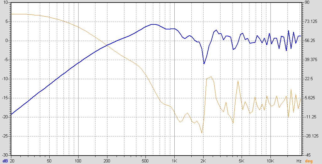
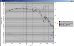
results shown below.
green is the non filtered response (on the baffle)
blue is with the actual impedance of the speakers
black is with the impedance doubled.
red I just added in, it is a second order bessel target at 2.8Khz (my crossover frequency, the final crossover is actually 4th order bessel at 2.8khz with some added components.
Tony.
Attachments
More than agree with that.The graphs above show all the symptoms of baffle step hump at about 650. A notch is not the best way to deal with it.
I had one project, where was about same picture ~600Hz. I've put notch there, got almost flat response, but after listening I removed it.
More than agree with that.
I had one project, where was about same picture ~600Hz. I've put notch there, got almost flat response, but after listening I removed it.
I have to run the edge again. But based on that graph I also agree with you. It needs BSC not a notch. However, when I ran a quick sweep test and from what I remember the real world measurements and graph (edge) are different. I will redo the actual measuremenmts.
BTW, I am new at this so your help is really appreciated and if I don't quite understand somethings you'll understand why
. My measurement technique is to use a sine sweep and behringer RTA. I also have the ability to use pink noise but the measurement jumps around a bit so I prefer a sweep. My calibrated mic is about 5 ft from the speaker about 3 ft off the ground. Is this correct way of doing it? Thanks Much!~!~~~
Hi,
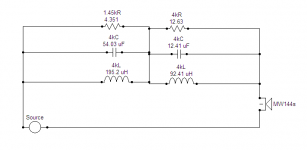
Here is an example of a parallel notch filter in series with the drivers,
to deal with the "dipole peak", which is not the same as the baffle
hump you get with a closed back baffle.
https://sites.google.com/site/undefinition/diy-sunflowers
rgds, sreten.
Here is an example of a parallel notch filter in series with the drivers,
to deal with the "dipole peak", which is not the same as the baffle
hump you get with a closed back baffle.
https://sites.google.com/site/undefinition/diy-sunflowers
rgds, sreten.
Last edited:
I have to run the edge again. But based on that graph I also agree with you. It needs BSC not a notch. However, when I ran a quick sweep test and from what I remember the real world measurements and graph (edge) are different. I will redo the actual measuremenmts.
BTW, I am new at this so your help is really appreciated and if I don't quite understand somethings you'll understand why
My measurement technique is to use a sine sweep and behringer RTA. I also have the ability to use pink noise but the measurement jumps around a bit so I prefer a sweep. My calibrated mic is about 5 ft from the speaker about 3 ft off the ground. Is this correct way of doing it? Thanks Much!~!~~~
If you have a calibrated mic, you are 99% there. Now download ARTA so you can do gated MLS measurements. Sweep (I use TrueRTA quick sweep) is fine for low bass, but everything else you need a gated measurement so you are not measuring the room, but the speaker. Of course, if yo can put your speaker on a 50 foot pool in a quiet valley, then sweep works fine.
It is an important discovery that the simulations do not always agree with the measurements. Two reasons. Measurements are not easy and simulations are only so good. Both are informative. The craft in speaker building is learning to interpret both and match that with your ears.
The best resource to really understand speaker measurements is D'Appolito Measuring Loudspeakers. Technical for beginners, advanced users know it. It is how you get from beginner to advanced. It really helps to understand what the measurements mean. Otherwise, you won't know when the model or measurement makes no sense.
I measure nearfield, one foot, 1M and listening position. I also measure on axis and at 15 degrees. I am voicing for on-axis, but looking to "fix" off axis. Subs I just measure at 1M. No reason to play around with them.
This forum is fantastic at helping those who put in effort and listen. A few of us do get a little rough on people who won't put in their own effort ( That big Y in DIY) or who are convinced their bright idea that violates the laws of physics has to be correct even though they have not tried it. I am a bit of a newbee, as I have only been at it for about 35 years off and on. I do have an advantage of a degree in electronics so struggling with the technical papers from those who really do know is not quite as tough as it once was. There are quite a few folks here who make their living at this. Somehow accountants seem to have difficulty with imaginary numbers and "S" planes.
I never had experience with open baffle projects, but supppose you must use 2 type of measurements: one is MLS as tvergeek offered, another similar to yours, as open baffle interacts with the room. Which combination in "flatnes" is best will be found after many listeting tests.My calibrated mic is about 5 ft from the speaker about 3 ft off the ground. Is this correct way of doing it?
MLS will show you errors in crossover design as well baffle reflections - at the beginning you can understand, what is speaker response in "simulated anechoic camera". But as it is OB, you must controll, how it interacts with the room.
In your measurements - nearfield is mic directly to cone - this is for you woofer, far field - about 1m from speaker on-axis. Recommend you to adjust height, that any part which can reflect (floor, ceiling, walls) must be on longer signal way. If you measure speaker at 1.6m and mic is 1m from floor you lower relable MLS measurmet will start from ~360Hz, but if you rize the speaker to 1.3m and measure from 1m it will be ~200Hz.
Taking me to school!!
TVR thanks for the honest (and sometimes humorous) response. I downloaded arta. Now I should give a complete picture of my equipment: I use a laptop. My mic is one that came with a Behringer DSP8024.
I looked at the Behringer manual I don't think it does gated measurements. Soooo, from doing a quick read of the arta help screen it looks like the mic gets connected to the laptop soundcard? Well my mic has balanced connectors. I will need to take more time to read the help (the Y in DIY) or of course you can tell me if I am on the right track . My first thought is i am going to have to find a way to go from balanced to mini plug? or just buy another mic?
Just curious, can I use the arta as a gated generator and do measurements with the Behringer?
TVR thanks for the honest (and sometimes humorous) response. I downloaded arta. Now I should give a complete picture of my equipment: I use a laptop. My mic is one that came with a Behringer DSP8024.
I looked at the Behringer manual I don't think it does gated measurements. Soooo, from doing a quick read of the arta help screen it looks like the mic gets connected to the laptop soundcard? Well my mic has balanced connectors. I will need to take more time to read the help (the Y in DIY
) or of course you can tell me if I am on the right track . My first thought is i am going to have to find a way to go from balanced to mini plug? or just buy another mic? Just curious, can I use the arta as a gated generator and do measurements with the Behringer?
- Status
- This old topic is closed. If you want to reopen this topic, contact a moderator using the "Report Post" button.
- Home
- Loudspeakers
- Multi-Way
- need help with passive notch filter design