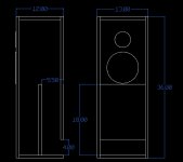
The illustration below is of a Toby Loudspeaker’s tower that I have had a pair of for ages. The only thing I am not sure of is the height and placement of the internal baffle. I cannot remember the model number, but I and a couple friends made a copy for each of us and have enjoyed them since 1989. To this day, I do not understand their operating principle. They are not ported (tuning would be too high) and not a true Transmission line either. They are, however, very efficient and can play solid down to 35Hz or so (driver Fs). The sound great with whatever mid-bass you put in them. We even ran 6x9 coaxials in a scrap pair and they were great – Toby did this as well I believe. What is the secret in the sauce?
Is it a 1/8 wave T-line? The fact that the port exit area is equal to the 8” mid-bass driver cone area, leads me to believe it is somewhere down that road. I could be completely wrong. I would like to see if the design is scalable and maybe for sub use. Anyone have any idea? It has been driving me nuts.
Is it a 1/8 wave T-line? The fact that the port exit area is equal to the 8” mid-bass driver cone area, leads me to believe it is somewhere down that road. I could be completely wrong. I would like to see if the design is scalable and maybe for sub use. Anyone have any idea? It has been driving me nuts.
Attachments
Ok, I can see that. Without the portion trapped behind the baffle, the enclosure is about the right size for the driver in a BR configuration. So, in stead of being loaded with a port working on air mass, it uses a T-line to load it with a portion of the backwave? Very interested here.
Toby Speakers of Fort Worth
Of course you can always call Toby and ask him. When I lived in the Fort Worth area I would visit his shop a few times a year to hear what new creations he had in work. An interesting dude and worth talking speakers with him.
Welcome to Toby Corp. of America
Of course you can always call Toby and ask him. When I lived in the Fort Worth area I would visit his shop a few times a year to hear what new creations he had in work. An interesting dude and worth talking speakers with him.
Welcome to Toby Corp. of America
Of course you can always call Toby and ask him. When I lived in the Fort Worth area I would visit his shop a few times a year to hear what new creations he had in work. An interesting dude and worth talking speakers with him.
Welcome to Toby Corp. of America
I used to work just a mile or so from his shop and have also stopped in a few times for either parts or to see what was cookin’. Once, I actually did ask him about this and his answer was “Become an audio engineer and all will become clear.” This could be taken a couple of ways, but I chose to take it as encouragement to learn more about the hobby that I love. Have I learned enough for this to become clear? Obviously not.

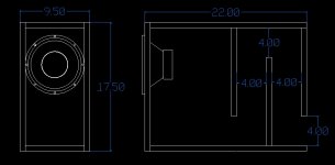
From the look of it, the 'port' looks to be a 1/16 wave t-line. ~20.5" length would be tuned to 41Hz or so. Would you even want such a thing? I am willing to experiment. Working on a spreadsheet to calc out an enclosure for my old JL 8" driver. I have it in a ported enclosure now that it sounds great in for comparison.
This is what I have come up with so far. Basically, it is the same enclosure volume as my ported one with a folded T-line stuck on the back. The line length is ~24" with a constant mouth area of 32sqin. The design lends itself to a simple build. The wifey needs some shelves built, so while im making a mess....
Attachments
Ok, just received scottmoose's post. I fully understand now that a TL is a 1/4 wave no matter what. That makes sense. Please disregard the previous two posts.
Since it is just a BR enclosure with a large port, is there any rhyme or reason for the dimensions of the port? Was/Is there a specific frequency being targeted? How does the length vs. width come into play?
Since it is just a BR enclosure with a large port, is there any rhyme or reason for the dimensions of the port? Was/Is there a specific frequency being targeted? How does the length vs. width come into play?
Scott deleted his previous post a minute or so after making it, but anyway, yes, just to confirm: a pipe that is sealed at one end and open at the other will always have a 1/4 wave fundamental. Period. You can set the length to a specific fraction of a given frequency, but it still possesses a 1/4 wave fundamental.
Leaving aside any esoteric aspects of the configuration, we're back to de rigure vented box math. Take your Vb, select duct CSA and appropriate length for that. You can work it out longhand, along with the 1/2 wavelength pipe resonances, or sim it in your choice of software -WinISD, Unibox, Hornrsp, Martin King's MathCAD software or whatever.
Leaving aside any esoteric aspects of the configuration, we're back to de rigure vented box math. Take your Vb, select duct CSA and appropriate length for that. You can work it out longhand, along with the 1/2 wavelength pipe resonances, or sim it in your choice of software -WinISD, Unibox, Hornrsp, Martin King's MathCAD software or whatever.
- Status
- This old topic is closed. If you want to reopen this topic, contact a moderator using the "Report Post" button.
- Home
- Loudspeakers
- Multi-Way
- What kind of enclosure is this?