I am going to take the box in to work tomorrow and make sure it is sealed completely by cauling all the joints. I need to open the route a little and perhaps it will sit tighter. I will also get some modeling clay to fill screw holes, just to make sure now air holes are available. I am done for the night. Wanted to screw around with Martin's sheets, but it seems like a waste of time till i get correct numbers.
The numbers I have are in post 379,381,and 382
FWIW, using BL to calculate Vad with MJK's sheets gets me dean on with the other numbers I have, but using Vas to calculate and check BL, multiple numbers are off, including BL, Cms, and Vas.
The numbers I have are in post 379,381,and 382
FWIW, using BL to calculate Vad with MJK's sheets gets me dean on with the other numbers I have, but using Vas to calculate and check BL, multiple numbers are off, including BL, Cms, and Vas.
Hmm, I found them in #377.
Anyway, the 381 mm 'D' spec is way off, being more in line with an 18" driver, so why Vas is way out.
Also, does the tester's doc state what the SoS, p0 it uses?
Regardless, using a known 416A Sd = 843.4 cm^2, 'D' = 327.7 mm, SoS = 344 m/s, p0 = 1.205 kg/m, I calc:
driver 1 = 410.5967 L
driver 2 = 444.4372 L
So you know you've done a good job measuring if you can get real close to these numbers.
In the meantime, using these for sims is plenty good enough.
GM
It seems I cannot even count right. I looked about proper measurement to use for diameter, and found conflicting results. Some said half way across the surround, others the full driver size. I fell in between with 15". I will retest using your updated size and see what happens.
It did?! I wonder. Using the previous specs + my calcs sim within a few liters to some known OEM measurements, but your new specs calc ~62% larger! either the new measurements are off and/or GPA didn't come close to OEM.
Also, we ideally still need Le at 1.0 kHz.
Regardless, as long as you can tolerate a big cab, the larger Vas means it can track the signal even better at very low power.
GM
Also, we ideally still need Le at 1.0 kHz.
Regardless, as long as you can tolerate a big cab, the larger Vas means it can track the signal even better at very low power.
GM
I just meant that MJK's sheets agreed with what the DATS system figured. In the program, it shows Le at 1kHz.
Here are the numbers
#1
Re - 6.25
Fs - 26.92
Qts - .319
Qes - .343
Qms - 4.573
Le - 1.678
Mms - 52.96g
Vas - 23.27ft^3
dB - 97.63 1W/m
BL - 12.78
#2
Re - 6.40
Fs - 25.57
Qts - .275
Qes - .294
Qms - 4.214
Le - 1.807
Mms - 52.94g
Vas - 25.8ft^3
dB - 98.08 1W/m
BL - 13.62
THey look like some 416-z numbers I have seen.
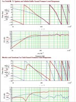
You may display more response detail in the Frequency graph. To do this reset the range of the graph. Clicking on it will allow you to enter different values where you have 110 & 60 now. I suggest 105 & 75 for 3 dB gradations or 104 & 84 for 2 dB gradations.
Varying Zdriver may have an effect upon the response ripple around 500 Hz.
You may consider a slot port as an alternate to an 8" diameter round port. Your locating the port close to the floor is favorable IMHO. I plan to investigate the use of an oversize slot port and stuff it lightly for tuning purposes. YMMV
Last edited:
Thanks for the comments. I am clearly new to the program. Is i tpossible to model a slot or do you just figure volume of the port. WinIsd lets you use double ports. With this, i was just playing with total vloume of the port. Next time i will post the impedance plot sas well to discuss what they mean an dhow they should look.
Your port idea is basically similar to aperiodic loading, correct. ZM posted a TQWT with large volume slot earlier.
Your port idea is basically similar to aperiodic loading, correct. ZM posted a TQWT with large volume slot earlier.
I have his newest sheets. In the MLTL worksheet, it only has an option for port radius and length. Further down, you can fine tune the box parameters for in room response, but none of the changes made there affect the upper response graphs which I showed. I assumed that this was to mean that if you wanted other shapes, you would have to just figure volume.
Varying Zdriver may have an effect upon the response ripple around 500 Hz.
You may consider a slot port as an alternate to an 8" diameter round port. Your locating the port close to the floor is favorable IMHO. I plan to investigate the use of an oversize slot port and stuff it lightly for tuning purposes. YMMV
Right on. MJK's math dictates a L*0.349 location, which only considers length while mine factors in CSA, so varies depending on the aspect ratio and since this cab doesn't have a very high one, it calculates L*0.487, even lower down than a golden ratio's L*0.46233, so no significant 1/4 WL vent loading unless the driver, vent is at the extreme ends. Plus, there’s the room’s vertical modes to consider WRT driver location.
Hmm, I figured a slot vent was planned since a 4" radius vent was located 2" off the bottom.
Coming from a 'critically' damped reflex vent oriented time, all my large vent alignments have/had them, so still recommend them when appropriate, though most folks want to take the extra time/effort required to tune a duct when they can temporarily slide in different length tubes to find the best overall vent length.
For sure, if a maximally flat alignment such as this one is used in a wall or corner loaded app it will tend to sound a bit 'boomy' [AKA 'west coast sound'] typical of many old Altec, JBL consumer products once BSC is dialed in.
GM
Couple of questions.
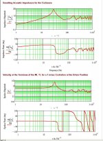
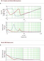
How important is consistency of wavelets(?) of the first two impedance graphs?
How do you determine port tuning? I have been using WinIsd. I dont know how to model aperiodic tuning.
Here is try using better box ratio. Cant figure out why acoustic impedances are so ugly and why there is nasty port phase issue
Attachments
")
- Home
- Loudspeakers
- Multi-Way
- Horn/TL combo