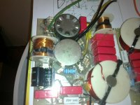
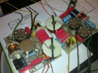
hi guys i bought my self a pair of veandersteen model 2's and i have been reading that a lot of people have been having problems with the crossover with no info on net and at a lost on how to fix the crossover i set about removing the crossover not a fun job so much glue a lot of care must be taken when doing this it is a double sided pcb i found it was glued with rubber base glue that was eating the pcb i will be using speaker sealing tape when puting it back i also foud a good replacment tweeter that meets up with the specks of the orgininal so hope this hepls drop me a message if you need more info
Attachments
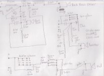
yes the open air one should read in the range of .9 ohm the other .5 the coils will never give problems the resistors there should be 2 lots of 3 10 ohm in parallel this = 3.3 ohms 3 watt i recommend changing both to a 3.3 ohm 3 watt non inductive cement type etc in the mide circuit i was unsure of a resistor to ground of the center should be change to the type as above they used 2 x 10 ohm in parallel witch = 5 ohms if this is right you can use a 5.6 ohm 5 watt can you confirm this with your crossover please mine was a bit brown the other resistor that was also a bit brown that i measured i was a little bit unsure of was in the tweeter circuit off the center of the L Pad to ground i think it was 19/20 ohmsHi Bigspeaker.
Of course it means a lot. Thank you very much")
Do you by any chance know values of coils in this xover ?
regards
confused:this is the only part of the whole crossover thats doing my head in changing all the resistors to the non inductive cement type makes the crossover pass the signal better without distortion etc i also recommend changing all the 4.7uf and the 3.3 uf with polly type caps the oil caps are the mainly for resistance correction so there fine to leave as is so if you could help me with this resistor i would appreciated thanks ian i will take photos of before and after hi again not sure if you got my last message something went wrong one air choke will read .9 of a ohm the other will read .5 or thereabouts etc they should not give trouble the big choke with the ferro rod is well made the polly switch is trouble and will need to be changed the 2 lots of 10 ohm resistors it is better to change them with 3.3 ohm cement type non inductive this is for the mid and tweeter circuit you may be able to help me i was a bit unsure about the resistor value in the tweeter circuit off the center of the LPad to ground it was a bit brown i worked it out to be 19/20 ohms and the other in the mid circuit off the center of the LPad to ground 2 10 ohm resistors in parallel =5 ohms thanks sorry for the 2nd reply if you got the first
- Status
- This old topic is closed. If you want to reopen this topic, contact a moderator using the "Report Post" button.