Give me the exact volume of your cabinet (this is minus the volume which the crossover, brace, drivers, port, etc. takes up) and the inner diameter of your port and I will model it for you.
Or, if you want to learn modeling software, download Unibox here:
UniBox - Unified Box Model for Loudspeaker Design - Kristian Ougaard
It's very easy to use. Do not use the T/S parameters from Seas. I recommend that you use Zaph's measurements here: http://www.zaphaudio.com/6.5test/ER18RNX-TS.gif
They are more accurate.
gornir,
Just saw this thread for the first time and read through it to see what it was about. A question and a comment or two. First it appears that the 2nd order filters that are shown in some of the responses are not inverted at the driver. That would seem to be an error as that would have a deep notch at the crossover point? And the comment that a 4th order filter has group delay that is worse than a 2nd order filter may be technically correct, the fact is that in most designs the alignment of the tweeter without a horn and a bass/mid could use that delay to get the time alignment much closer than you would ever achieve with a simple 2nd order filter.
But those comments aside my actual question for you is about your Zobel or conjugate correction of the entire system. I have never seen this network in that position, one Zobel correcting for two devices simultaneously! What is your thinking here, why is there not two impedance corrections, one for each device, how can this work to correct both impedance rises at the same time with this design. That was the most interesting design aspect of this entire thread to me. I completely understand what you are attempting to do with the notch filters but not that one aspect of your xo design. Please do elucidate on that one feature.
The trick to good bass is to shoot for lower Q and not have a "sharp knee," or hump in the response. The shallower the roll-off, the better the sound. However, it has to be within reason as to not sacrifice F3 too much. Tuning too low is also not recommended as your group delay will become worse. It's all about the sacrifices and balance.
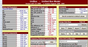
In picture, unibox1, you can see the Seas ER18RNX data that I've entered using Zaph's T/S measurements.
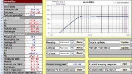
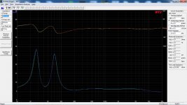
In unibox2 you can see the smooth roll-off in a heavily stuffed enclosure. I've used your port of 5.4cm diameter and 14cm length. I've also set the internal volume to 15 liters.
Fb = 46Hz
F3 = 52Hz
F6 = 43Hz
F10 = 36Hz
Not bad at all.
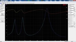
In unibox 3 you can see what the response looks like if the enclosure is only lined, but not stuffed. Again, the port and the net volume has been forced to the data which you gave me. Here we have a slight response bump and a much sharper knee. While it might not bee a big deal in a medium to large room... In a smaller room, the bass might become slightly boomy (one note) and option one may indeed sound better.
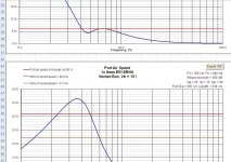
In unibox4 (this applies only to the first option) you can see the port air speed and cone excursion. At 80 watts (ER18RNX's rated max power), the woofer stays within its linear excursion and only unloads below 40Hz. There's usually not that much music content below 40Hz, so it should not be a concern. For home theater, the DSP's bass management should be used and set to THX's standard of 80Hz. At that point, you can dump as much power as you want.
At 80 watts, we do exceed the recommended port air speed. However, it's unlikely that port noise will be present with normal music. A 40Hz continuous sinewave at full power might be a different story, but that is not normal conditions. One way to lower the port air speed is to use two 5.4cm ports, if you can fit them in the cabinet, as they will now have to be much longer.
A little advice on box dampening... From my personal experience and measurements, fiberfill, foam, Acousta-Stuf, etc. does very little to absorb reflections and standing waves. This is what I found to work the best over the years:
Line all cabinet walls with Dynamat (expensive), or similar (less expensive) product. Then, Owens Corning 703 hard fiberglass 1" panels (the best) (line all walls) works wonders for absorbing reflections: Owens Corning 703 Rigid Fiberglass Board, 1 Inch (6PK)
And finally, you have to deal with standing waves. If you read Mark's write-up, he recommends stuffing the box and also creating a layer between the port(s) and woofer. It's a very good idea. Standing waves and reflected midrange frequencies can escape the port(s) and color the sound. A bad port will measure like this (in red trace): http://www.stereophile.com/images/711DASSfig3.jpg
You can clearly see a huge resonance peak at 200Hz. And here is a well designed port (again in red): http://www.stereophile.com/images/712Dalifig3.jpg
Notice, it has zero excess resonances.
For a small two-way speaker like the ER18DXT, I use a rolled up sheet (120cm X 60cm) of medium sized (10mm bubbles) bubble wrap. Make sure you position it between the woofer and the port(s), but do not obstruct the port openings! This amount of bubble wrap will not effect your volume much and will also act as a heavy fill. Best of all worlds.
In picture, unibox1, you can see the Seas ER18RNX data that I've entered using Zaph's T/S measurements.
In unibox2 you can see the smooth roll-off in a heavily stuffed enclosure. I've used your port of 5.4cm diameter and 14cm length. I've also set the internal volume to 15 liters.
Fb = 46Hz
F3 = 52Hz
F6 = 43Hz
F10 = 36Hz
Not bad at all.
In unibox 3 you can see what the response looks like if the enclosure is only lined, but not stuffed. Again, the port and the net volume has been forced to the data which you gave me. Here we have a slight response bump and a much sharper knee. While it might not bee a big deal in a medium to large room... In a smaller room, the bass might become slightly boomy (one note) and option one may indeed sound better.
In unibox4 (this applies only to the first option) you can see the port air speed and cone excursion. At 80 watts (ER18RNX's rated max power), the woofer stays within its linear excursion and only unloads below 40Hz. There's usually not that much music content below 40Hz, so it should not be a concern. For home theater, the DSP's bass management should be used and set to THX's standard of 80Hz. At that point, you can dump as much power as you want.
At 80 watts, we do exceed the recommended port air speed. However, it's unlikely that port noise will be present with normal music. A 40Hz continuous sinewave at full power might be a different story, but that is not normal conditions. One way to lower the port air speed is to use two 5.4cm ports, if you can fit them in the cabinet, as they will now have to be much longer.
A little advice on box dampening... From my personal experience and measurements, fiberfill, foam, Acousta-Stuf, etc. does very little to absorb reflections and standing waves. This is what I found to work the best over the years:
Line all cabinet walls with Dynamat (expensive), or similar (less expensive) product. Then, Owens Corning 703 hard fiberglass 1" panels (the best) (line all walls) works wonders for absorbing reflections: Owens Corning 703 Rigid Fiberglass Board, 1 Inch (6PK)
And finally, you have to deal with standing waves. If you read Mark's write-up, he recommends stuffing the box and also creating a layer between the port(s) and woofer. It's a very good idea. Standing waves and reflected midrange frequencies can escape the port(s) and color the sound. A bad port will measure like this (in red trace): http://www.stereophile.com/images/711DASSfig3.jpg
You can clearly see a huge resonance peak at 200Hz. And here is a well designed port (again in red): http://www.stereophile.com/images/712Dalifig3.jpg
Notice, it has zero excess resonances.
For a small two-way speaker like the ER18DXT, I use a rolled up sheet (120cm X 60cm) of medium sized (10mm bubbles) bubble wrap. Make sure you position it between the woofer and the port(s), but do not obstruct the port openings! This amount of bubble wrap will not effect your volume much and will also act as a heavy fill. Best of all worlds.
Attachments

Last edited:
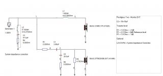
But those comments aside my actual question for you is about your Zobel or conjugate correction of the entire system. I have never seen this network in that position, one Zobel correcting for two devices simultaneously! What is your thinking here, why is there not two impedance corrections, one for each device, how can this work to correct both impedance rises at the same time with this design. That was the most interesting design aspect of this entire thread to me. I completely understand what you are attempting to do with the notch filters but not that one aspect of your xo design. Please do elucidate on that one feature.
You put the L2+C3+R4 circuit across the speaker input terminal before the actual cross-over filter for a total system impedance correction (picture1). See picture 2 and 3 for the effect of it.
Why use it? Actually this is an optional feature and isn't really needed, but can be good when using a tube amp.
Regards
/Göran
Attachments
Gornir, any chance we can see a "transient perfect" two-way design from you in the future?
Never say never, but it's not the easiest design top pull off successfully.
")
/Göran
Never say never, but it's not the easiest design top pull off successfully.
/Göran
I've been looking at your website, you have tons of awesome designs! Revelation Two – Monitor MkII is so tempting
I've played with Unibox.
All parameters are same as you say Ridikas.
I have entered current port diameter of 5cm, in red graph of port length I have 12.54- it means I need to cut port to that length ? And in design by vb fb and q is different again.
And yes, according to the simulation, I need heavy stuffing of box.
I had a look on dynamat- but there is consensus if box is well braces (my - is, as I glued every panel with 3 dowels on each joint with well made brace)it is not necessary.
Next is a fiberglass. If I get uk similar, should I still use wool or any other filler together ?
Bubble wrap is to put between driver and a brace ?
Thank you
You've told me that the inner port diameter was 5.4cm previously, so yes, the length will be different in your modeling if you're using 5cm...
You can use wool, but it really doesn't kill standing waves. From years of experience, I can tell you the bubble wrap works very well.
You can use wool, but it really doesn't kill standing waves. From years of experience, I can tell you the bubble wrap works very well.
OK, I've modeled the new port 5cm inner diameter and 14cm long. In a 15 liter cabinet, with walls covered, I get the following:
Fb = 46Hz
F3 = 47Hz
F6 = 41Hz
F10 = 35Hz
With a peak of only 0.3dB. Fairly insignificant.
Since your box will be semi-stuffed, because you want to kill standing waves, resonances/noises leaking out of the ports, etc., in a heavy filled enclosure it looks like this:
Fb = 43Hz
F3 = 54Hz
F6 = 41Hz
F10 = 34Hz
With no peaking. This is a low Q, smooth roll-off.
And in a box with the amount of stuffing between heavy fill and walls covered, I get:
Fb = 45Hz
F3 = 49Hz
F6 = 41Hz
F10 = 35Hz
Again with no peaking, but with a sharper knee (higher Q) roll-off.
Basically the differences are small and your design is not sensitive to slight variances. Do NOT cut the port. Leave it as it is.
Line the walls with 0.75"-1.00" rigid fiberglass panels (Corning 703) and stick a roll of bubble wrap (a sheet of 120cm by 60cm) in the center of the box. Try to position it between the ports and the woofer, but do NOT obstruct the port openings.
You are amazing !
Thank you for helping out with port.
BTW I am not in a hurry so if bigger diameter (and flared) port is better I can order it.
But if you say it is fine- it is fine then
(handshake)
Build with what you have first and listen. If it sounds good, leave it. If there are noises/chuffing then you can always install a flared port later.
- Status
- This old topic is closed. If you want to reopen this topic, contact a moderator using the "Report Post" button.
- Home
- Loudspeakers
- Multi-Way
- Erse inductors in europe ?