My multis are for the 1.4" drivers.
Weren't all multi's a 1.4"?
That would be a happy coincidence for me
Would you guys suggest copying a proven existing design or making new one?
I think my issue will be getting the exponential curve sorted. From there I would transfer it to a thick plastic and use that to my sections. I think I'll make up a former out of a dowel with squares threaded over it that correspond to the shape of the horn. That 'should' be easily repeatable (as its not a full replica exponential curve on 4 sides) so I can have several stood in a block of wood and just rotate them to work on the cell and do several at a time
It'll be slow going but there will be minimal clear up and I can do in on the dining table
As far as I know, yes.Weren't all multi's a 1.4"?
If one could find 'Blue' foam - used to come in 8ft x 4ft sheets, 1, 2 and 4 inches thick - one could 'Hot Wire' the cell's walls with the curve already there AND with feather edges....... one could then 'press' mould a skin on both sides, the press forms being hot-wired from the wall templates.
This technique works REALLY well, tis how a lot of high performance aircraft wing skins are made.
If one can find decent NiChrome wire for the cutting bow, one could cut a form to the inside dims of a cell to support the cell walls on while slopping bonding agents around.
This technique works REALLY well, tis how a lot of high performance aircraft wing skins are made.
If one can find decent NiChrome wire for the cutting bow, one could cut a form to the inside dims of a cell to support the cell walls on while slopping bonding agents around.
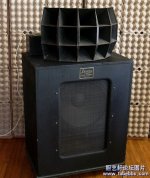
Dunno. Here is some eye candy. Dont kow how they sound, but they look wicked cool.
How is that for a sound room!
Your package goes out today.
SO MUCH WOOD!!!
One could even hot wire the compression driver to cell mouth manifold, chop that in half length ways, line with paper, apply glossy finish, bond it back to a whole, fix mounting plates/studs etc, tis only a matter of marking divisions on the templates to 'time in movement' the hot bow to......... same technique as cutting tapered model wing cores.
Weren't all multi's a 1.4"?
No, the Lansing 800 series [808 thru 1508] were all 1". Only the 808 is fairly well known though due to being part of the Lansing Iconic and later the original horn for the Altec 800 VOTT.
The once thought [by me anyway] just a catalog number 1508:
GM
Attachments
Ok, paper is the way forward. I'll leave off the 8 Cell ePay special because I can have more fun sticking stuff to my fingers and the cat. Also it should come in under budget (I hope)
Looking at this calculator Single Driver Website I need to understand some finer details....
Throat Area (cm2) - is this for a single cell or am I calculating for the entire structure then dividing it up?
Flare Frequency - as above and how does one go about picking the frequency? The ePay specials for example were a 300hz flare and I'm looking at 65hz as the lowest usable freq of my driver
M (The degree of hyperbolic influence) - I assume pure exponential?
Cabinet Width - should I specify the actual cabinet or reduce it to the ideal cell size as I'm making several to for a whole horn?
Thanks for baring with me fellas. They upped my bipolar drugs and I'm felling like a barely functioning idiot
This is starting to get interesting.
Perhaps this will help
http://rocketsciencecanada.com/Sound/Horns/Info_SizeShape.asp
Perhaps this will help
http://rocketsciencecanada.com/Sound/Horns/Info_SizeShape.asp
Last edited:
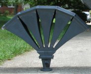
If you want to build a 1005, I can measure for you. 803 I could drag down out of the loft.
Can't help with any others.
1005: Each cell mouth is 6.25"x6.25"
Cell length is 15"
Would have to pull them apart to measure the size of each cell at the join. It's less than 1", for sure. You can see the horn profile in the photo below.
Can't help with any others.
1005: Each cell mouth is 6.25"x6.25"
Cell length is 15"
Would have to pull them apart to measure the size of each cell at the join. It's less than 1", for sure. You can see the horn profile in the photo below.
Attachments
ohh wow, the guy had to put this song for the demo?But it IS!
JBL 4355 speakers restored by Kenrick Sound has been delivered to Mr. Abe's room - YouTube
Ok.. not really, but it's not exactly large either.
..I don't know Japanese (at all), but I suspect the movers (just before unwrapping the 1st one) were saying something along the lines of:
"you want us to put this where?"
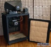
JRKO, For your inspiration
Very cool!
Those are NICE. What is so depressing about it is those horns are a first effort before the guy makes 1505's!!! Some people are so talented........damn them
Now for some ideas to test:
for initial joining of the sides of the cell together how about maybe 4 or 5 thin tabs as part of cell cutout. These are then glued to the next side etc so you have a fairly dimensionally stable base upon which to lay your mache strips.
Need to figure out if its better to use slightly watered down PVA, wall paper paste (anti fungal goodness), large strips or thin, thick or thin paper thru out or maybe mixed.
another thought would be to lay each layer at 90deg to build up a sound structure.
Also thought of embedding wire between layers every now and then. Or even better take Petter's 'ring clamp' idea and make squares of stiff wire to fit around the outside to keep the the cell strong
It obviously needs to be self supporting and I think will get stronger as more cells are joined together. If memory serves, paper mache ends up with a stiff tap sound moving to dull thud the thicker it gets, but I doubt we need to go much past 2-3mm if 3mm ply or MDF works, paper 'should' be stiffer. How many layers to you guys see as being required?
Last edited:
- Status
- This old topic is closed. If you want to reopen this topic, contact a moderator using the "Report Post" button.
- Home
- Loudspeakers
- Multi-Way
- And Now For Something REALLY BIG