Helmholtz Resonator Inside a Sealed Cabinet
What will be the result if inside a sealed enclosure we install a Helmholtz resonator tuned at the frequency of the system impedance peak?
Most probably it has been long done, but Google and forum search didn't return an examined example of such system.
Please, don't feel limited only to the matching fb's of both systems, the resonator could be tuned lower, higher or double tuned etc. Any experience, thoughts and analysis are welcome.")
Best regards!
What will be the result if inside a sealed enclosure we install a Helmholtz resonator tuned at the frequency of the system impedance peak?
Most probably it has been long done, but Google and forum search didn't return an examined example of such system.
Please, don't feel limited only to the matching fb's of both systems, the resonator could be tuned lower, higher or double tuned etc. Any experience, thoughts and analysis are welcome.
Best regards!
It puts a notch in the frequency response at the Helmholtz resonance frequency.
It actually works like a standard ported enclosure in that the Helmholtz resonance loads the driver, reducing its excursion, and thus reduces the radiation from the front of the driver. But in the standard ported enclosure the drop in driver output is compensated for by the output from the port. With a completely enclosed resonator you don't get the additional output, so the resultant output SPL curve is that of a sealed enclosure with a "notch" at the tuning frequency of the resonator. (More accurately, at the resonant frequency of the two coupled volumes, as they affect each other.)
You might do this if you wanted to tame a driver resonance, but this is better done with an electrical notch filter ahead of the speaker. It is better to reduce the resonance exciting energy before it gets to the driver, rather than trying to damp it afterwards.
Last edited:
Thanks, I wasn't able to decide between loading and unloading.
The example that made me thinking is high Qts, low Fs bass driver.
There is pretty good probability that the Akabak software is able to simulate such system, only that someone more knowledgeable than me must get interested and write the code.
As for weighting the two alternatives, electrical and mechanical notch, maybe they are on par by cost or even with advantage in favor of the mechanical one. It is real itch to see an impedance curve modified with such a device.
Best regards!
If you figure out a way to reduce the cone resonance (about 2.5kHz) of many of the 8" Full Range light comne drivers with a simple set of "passive tuned notch resonators", you will have many happy people indeed, and maybe also customers.
There was some methods and technical evaluations done on this some years ago but I've never been able to find it either.
There was some methods and technical evaluations done on this some years ago but I've never been able to find it either.
Sounds like allot tougher problem for a passive mechanical system.
With low frequencies and a resonator, there is no problem with the coupling and the magnitude as well. Coupling will occur irrespective of the resonator placement and magnitude will depend on pipe area.
Further, there are designs with enclosed volume and pipe even TL ones. Only I have never seen tougher explanation of those.
At 2.5 kHz with considerably shorter waves, the path is obviously with a notch filter. The same applies to paper cone sealed chassis tweeters, all have resonance between 1 and 2 kHz that leaves artifacts no matter how high and steep you cross them thus the necessity to always address the phenomenon.
But here the topic is using a high Qts nicely voiced bass driver in a reasonably sized sealed enclosure. In any case they are not suitable for anything else and produce a nasty bump in the response and a big impedance peak. The same actually applies to any type of enclosure with such driver, not only sealed.
Best regards.
Last edited:
Hi,
the german diy magazine HobbyHifi discussed this issue a couple of years ago as a measure against standing wave artefacts in popular thin and high casings.
Seemingly it worked well, at least measurement-wise. It´s kind of mechanical alternative for a electronic notch-filter.
jauu
Calvin
the german diy magazine HobbyHifi discussed this issue a couple of years ago as a measure against standing wave artefacts in popular thin and high casings.
Seemingly it worked well, at least measurement-wise. It´s kind of mechanical alternative for a electronic notch-filter.
jauu
Calvin
One bonus of using an acoustical filter is possibly better distortion performance. If a (distortion) harmonic of a fundamental hits the resonance peak and you only used notch in the electrical signal, it is not attenuated. The acoustical solution would notch out the distortion product also. Same principle as reducing distortion in low frequency bandpass and horn enclosures with their acoustic low pass function working at reducing all out-of-band content.
Hi,
the german diy magazine HobbyHifi discussed this issue a couple of years ago as a measure against standing wave artefacts in popular thin and high casings.
Seemingly it worked well, at least measurement-wise. ...
A good fix for the problem of standing waves in long enclosures is the Double Chamber Reflex.
Look here, and also search DiyAudio:
DCR
... There is pretty good probability that the Akabak software is able to simulate such system, only that someone more knowledgeable than me must get interested and write the code.
Try this:
Code:
Def_Driver 'Driver'
  Sd=220.00cm2
  Bl=7.00Tm
  Cms=1.00E-03m/N
  Rms=1.00Ns/m
  fs=37.6374Hz  |Mmd = 16.00g not recognised by AkAbak, fs calculated and used instead
  Le=0.10mH
  Re=7.50ohm
  ExpoLe=1


| Sealed enclosure with an internal Helmholtz resonator tuned to the system's Fs.
System 'S1'

  Driver 'D1'  Def='Driver'  Node=1=0=2=3

  Enclosure    'E1'  Node=2
    Vb=77L  Lb=25cm

  Radiator  'Rad1'  Def='D1'    Node=3

  Duct    'Du1'  Node=2=4
    dD=2cm  Len=4cm

  Enclosure    'E2'  Node=4
  Vb=10L  Lb=10cm
Note that the resonator and its port are impractically sized - this is a proof of concept only.
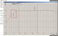
Thanks for that! If the effect of the resonator is the dip encircled in red on the simulation, then it works!
This is very cool
There are so many good sounding drivers with decently low Fs lacking the magnet power to be used in any enclosure. In vented it becomes even worse with high Qts drivers, but I can't simulate the added resonator in vented enclosure as well.
Since I posted the thread, there is another suspicion in my head... What if the resonator is double tuned? I know, that there is no such thing as double tuned single enclosure. It is always a sum of the two vents acting as one with different proportions.
But it could be possible to tune the resonator once to extract the bump out of the response of the high Qts driver and once more to the surroundig environment to aid the LF response. (DCAAV or DBR Fostex - the middle example from the link to DCR http://www.claudionegro.com/projects/speaker/dcr/dcr.html posted above)
Another thought is application in enclosures for midrange drivers. Again there are allot of beautifully sounding fullrange and midrange drivers that produce a bump in sealed enclosures. Examples are some TB drivers with Qts around 0.7 as well as Visaton B200 if asked to serve as a midrange in 5-10L enclosure. Not to mention some internal cabinet reflections and resonances that occur at specific frequencies that can be cured with such resonator.
The beauty of the method is that it is as easy to construct as double bottom and a pipe attached to it.
We could improve the Akabak model in order to be usable by anyone. (or at least explain how to substitute the variables for different examples to ones like me )
Link to the Akabak download page: Download - Akabak
Best Regards!
p.s. I'm excited
This is very cool
There are so many good sounding drivers with decently low Fs lacking the magnet power to be used in any enclosure. In vented it becomes even worse with high Qts drivers, but I can't simulate the added resonator in vented enclosure as well.
Since I posted the thread, there is another suspicion in my head... What if the resonator is double tuned? I know, that there is no such thing as double tuned single enclosure. It is always a sum of the two vents acting as one with different proportions.
But it could be possible to tune the resonator once to extract the bump out of the response of the high Qts driver and once more to the surroundig environment to aid the LF response. (DCAAV or DBR Fostex - the middle example from the link to DCR http://www.claudionegro.com/projects/speaker/dcr/dcr.html posted above)
Another thought is application in enclosures for midrange drivers. Again there are allot of beautifully sounding fullrange and midrange drivers that produce a bump in sealed enclosures. Examples are some TB drivers with Qts around 0.7 as well as Visaton B200 if asked to serve as a midrange in 5-10L enclosure. Not to mention some internal cabinet reflections and resonances that occur at specific frequencies that can be cured with such resonator.
The beauty of the method is that it is as easy to construct as double bottom and a pipe attached to it.
We could improve the Akabak model in order to be usable by anyone. (or at least explain how to substitute the variables for different examples to ones like me
)Link to the Akabak download page: Download - Akabak
Best Regards!
p.s. I'm excited
Attachments
Last edited:
Dahlquist DQ10 woofer enclosure with internal chambers
It's been a while since I looked at one, but I believe the woofer enclosure of the Dahlquist DQ10 had two internal damping chambers. They were made by boarding off ends of the enclosure leaving a small gap with one wall to make the rectangular vent openings. There was damping material in these damping chambers.
It's been a while since I looked at one, but I believe the woofer enclosure of the Dahlquist DQ10 had two internal damping chambers. They were made by boarding off ends of the enclosure leaving a small gap with one wall to make the rectangular vent openings. There was damping material in these damping chambers.
Hi Don.Try this:
Code:... fs=37.6374Hz |Mmd = 16.00g not recognised by AkAbak, fs calculated and used instead ...
Hate to go OT a bit, but I have been struggling at times with AkAbak not accepting certain values, such as Mmd, and I was wondering if you could explain that a bit, and your workaround.
Hi Don.
Hate to go OT a bit, but I have been struggling at times with AkAbak not accepting certain values, such as Mmd, and I was wondering if you could explain that a bit, and your workaround.
I didn't do the workaround - the AkAbak model I used as a starting point was an export from Hornresp, which does the conversion during the export. I haven't looked into it, I suspect Hornresp uses a different subset of driver parameters for calculations than AkAbak does.
Now it got even more confusing. Don't look at me, I just copy-pasted and pushed a button.
The only suspicion I had, was why the dip has such small extent, I would expect something like half octave at least. For instance if Fb is 50 Hz, then it should be between 37.5 and 75 Hz.
Don't look at me, I just copy-pasted and pushed a button.The only suspicion I had, was why the dip has such small extent, I would expect something like half octave at least. For instance if Fb is 50 Hz, then it should be between 37.5 and 75 Hz.
I think that using resonators to take the "hump" out of high Qts driver responses is going to be problematic to implement. Standard Helmholtz resonators have too high a Q value, as you see in the results - a very narrow notch. (By the way, when working with bass units, I find it useful to reduce the frequency range of the AkAbak graphing function to, say, 200 Hz instead of 20 KHz.)
You might be able to lower the Q of the resonator by stuffing it, similar to the Dahlqist DQ10 speaker scheme mentioned by bolserst.
Maybe you could produce an AkAbak script for a driver and enclosure that you would like to reduce peaks in, and we can try some ideas on it. If you're not proficient with AkAbak, do it in Hornresp and export it, or do it in some other software and provide the driver parameters and box dimensions.
Perhaps you could further reduce the Q by venting into your stuffed second chamber through a vario-vent.
Speaking of which - does anyone know how to describe a vario-vent in AkAbak? I suppose one would describe a duct with a modified impedance - not sure how that's done...
Speaking of which - does anyone know how to describe a vario-vent in AkAbak? I suppose one would describe a duct with a modified impedance - not sure how that's done...
I didn't do the workaround - the AkAbak model I used as a starting point was an export from Hornresp, which does the conversion during the export. I haven't looked into it, I suspect Hornresp uses a different subset of driver parameters for calculations than AkAbak does.
To keep this from going any more off topic I am going to switch this over to this thread... http://www.diyaudio.com/forums/multi-way/90362-akabak-simulator-5.html
I see a cardioid design with a helmholtz resonater in the cabinet. I had assumed as it is "in parallel" with the driver it was to flatten the resonant impedance spike of the driver thus ensuring more accurate delay and therefore extended cardioid response. Or am I way off the mark?!
Hi T101,
IIRC, some time between the years 2000 to 2010 a patent was reviewed in the industry magazine Voice Coil (Voice Coil Magazine) that described the use of Helmholtz resonators inside a loudspeaker enclosure to reduce the effects of standing waves. This review or the patent may provide you with some greater insight as to their usage. Hope this helps.
Peter
- Status
- This old topic is closed. If you want to reopen this topic, contact a moderator using the "Report Post" button.
- Home
- Loudspeakers
- Multi-Way
- Helmholtz Resonator Inside a Sealed Cabinet