It doesn't matter. Go for a nice looking 30L box filled with recycled cloth (main content wool) wadding in a see-through cloth. It looks like a loose pillow.
Apply the active crossovers and have a listen. If it is too dark and boomy, buy 10-12 cheap ~100uf electrolitic capacitors (not less than 20V rating) per speaker and try different arrangements as follows:
In all cases you connect two capacitors in series with opposite polarity to each other in the woofer + terminal.
With polarised eclectrolitic capacitors 100+100 in series is again 100uf - remember that.
When you connect two capacitors in parallel the capacitance doubles.
The required capacitance in series with the woofer will be somewhere in the 300 to 600 uf range.
So you should start with 6 ~100 uf capacitors grouped 3 by 3 in parallel and the two 3's in series to each other.
If the capacitance is too low, the speakers will sound tiny, if it is too much, you won't be able to hear difference. Make it just right and it will sound sweet with well articulated bass.
The trick with the capacitors is for overcoming the nasty peak in the LF that every system with a driver with Qts above 0.7 produces.") Visaton, KEF and etc. use that approach shamelessly for the past 30-40 or so years...
Visaton, KEF and etc. use that approach shamelessly for the past 30-40 or so years...
If I am wrong with the capacitance values for 4 ohm driver, let some of the more knowledgeable members correct me.
Best regards and go for your extremely cheap and hopefully good sounding system!
p.s. since I like cone tweeters and since this one is regarded in a magasine, I wouldn't hesitate to indulge myself with a $~50 system that sounds funnily good
Apply the active crossovers and have a listen. If it is too dark and boomy, buy 10-12 cheap ~100uf electrolitic capacitors (not less than 20V rating) per speaker and try different arrangements as follows:
In all cases you connect two capacitors in series with opposite polarity to each other in the woofer + terminal.
With polarised eclectrolitic capacitors 100+100 in series is again 100uf - remember that.
When you connect two capacitors in parallel the capacitance doubles.
The required capacitance in series with the woofer will be somewhere in the 300 to 600 uf range.
So you should start with 6 ~100 uf capacitors grouped 3 by 3 in parallel and the two 3's in series to each other.
If the capacitance is too low, the speakers will sound tiny, if it is too much, you won't be able to hear difference. Make it just right and it will sound sweet with well articulated bass.
The trick with the capacitors is for overcoming the nasty peak in the LF that every system with a driver with Qts above 0.7 produces.
Visaton, KEF and etc. use that approach shamelessly for the past 30-40 or so years...If I am wrong with the capacitance values for 4 ohm driver, let some of the more knowledgeable members correct me.
Best regards and go for your extremely cheap and hopefully good sounding system!
p.s. since I like cone tweeters and since this one is regarded in a magasine, I wouldn't hesitate to indulge myself with a $~50 system that sounds funnily good
Last edited:
Last edited:
That's a great link for measuring speaker parameters, but very technical and most people don't have the needed equipment to do this. There are some "old school" ways to get a general idea of the speakers characteristics:
Gently push on the woofer cone (evenly) and "feel" how stiff the suspension is. It takes experience to judge if this feels "stiff" or "loose" (or compare to another woofer of known specs) This helps choose a box size ("stiff" needs larger box and lots of stuffing material) Now short out the speaker wire terminals with something metal (key) and "feel" the stiffness again. It should feel a bit stiffer and more "damped". The more change you feel, the better electrical dampening. A stiff speaker and poor damping is not a good thing. Now make a box (see link for picture) and "feel" how stiff the woofer is when sitting on box. These are very crude methods, but easy to do and cheap! Finally, you can use a test CD (or make one) that has different tones and check for strong peaks (both free air and when sitting on box) This will get you close enough to choose a box size
Gently push on the woofer cone (evenly) and "feel" how stiff the suspension is. It takes experience to judge if this feels "stiff" or "loose" (or compare to another woofer of known specs) This helps choose a box size ("stiff" needs larger box and lots of stuffing material) Now short out the speaker wire terminals with something metal (key) and "feel" the stiffness again. It should feel a bit stiffer and more "damped". The more change you feel, the better electrical dampening. A stiff speaker and poor damping is not a good thing. Now make a box (see link for picture) and "feel" how stiff the woofer is when sitting on box. These are very crude methods, but easy to do and cheap! Finally, you can use a test CD (or make one) that has different tones and check for strong peaks (both free air and when sitting on box) This will get you close enough to choose a box size
Two 100uf caps in series = 50uf.
Mac
Crossovers for dummies, DIY Practical Guide to the loudspeaker crossover - The Book Worm
Not sure it applies to polarized electrolytic capacitors. Even if it does, he will arrive at the required capacitance in the end. Either way, this is just for cost saving. I don't think it is a good idea to buy 300 to 600 uf non polarized non electrolytic foil capacitors as they will cost more than the system. Reputable brands have done it this way with the opposite polarity electrolytes.
If he finds non polarized electrolytes it would be better and the series connection will be avoided.
Best regards!
Here is the science behind that:
Can you make a non-polar electrolytic capacitor out of two regular electrolytic capacitors? - Electrical Engineering
http://electrochem.cwru.edu/encycl/misc/c04-appguide.pdf - linked in the above article.
So, you are right and I am right as well
For those who got confused by the capacitor saga.The series capacitor is used to cure the output of a system that not only has Qtc of over 0.707, but is employing a driver with Qts of over 0.707. Then the peak in the response is very exaggerated:
Allot more than the violet curve and falls steeper below Fc.
Source: Speaker Box Calculations
The Qtc of a system cannot be lower than the Qts of the driver.
Further, there is a common misunderstanding that high Qts drivers are only suited for acoustic suspension/sealed box. This is wrong.
- relatively low Qts, heavy membrane and low Fs drivers are best suited for sealed enclosure! And the EBP (Fs/Qes) is the best other reference value whether a driver is suitable for sealed enclosure. A 0.28 Qts, 0.3 Qes driver with 17 Hz resonance will have an EBP of 59 - merely above the absolute minimum for vented enclosure... which makes it better suited for sealed despite the lowish Qts.
High Qts drivers are suitable for midranges, open baffle, H and U frame (vintage radio receivers), infinite baffle and lossy boxes (aperiodic/labirinth/vibrating thin walls).
There is no contradiction between good sounding driver and high Qts, so some designers and hobbyists use high Qts drivers in conventional sealed enclosures by making use of the capacitor trick.
The capacitor trick as already said cures the nasty peak above and around Fc in the response, makes the roll off less steep and can even bring F-3db below Fc.
So again, go for it with the uberly cheap drivers and share the results
Best regards!
Can you make a non-polar electrolytic capacitor out of two regular electrolytic capacitors? - Electrical Engineering
From:If two, same-value, aluminum electrolytic capacitors are connected in series, back-to-back with the positive terminals or the negative terminals connected, the resulting single capacitor is a non-polar capacitor with half the capacitance.
http://electrochem.cwru.edu/encycl/misc/c04-appguide.pdf - linked in the above article.
So, you are right and I am right as well
For those who got confused by the capacitor saga.The series capacitor is used to cure the output of a system that not only has Qtc of over 0.707, but is employing a driver with Qts of over 0.707. Then the peak in the response is very exaggerated:
Allot more than the violet curve and falls steeper below Fc.
Qtc:
Qtc is the total Q of the speaker in an enclosure including all system resistances. A Qtc of .707 is the most common and generally produces the flattest frequency response with approximately a 6dB/octave rolloff. Higher values of Qtc will give a peak in the output with a sharper rolloff. A lower Qtc will start to roll off earlier and will roll off at a slower rate. If you don't know what Qtc you need, start with a Qtc of .707.
Source: Speaker Box Calculations
The Qtc of a system cannot be lower than the Qts of the driver.
Further, there is a common misunderstanding that high Qts drivers are only suited for acoustic suspension/sealed box. This is wrong.
- relatively low Qts, heavy membrane and low Fs drivers are best suited for sealed enclosure! And the EBP (Fs/Qes) is the best other reference value whether a driver is suitable for sealed enclosure. A 0.28 Qts, 0.3 Qes driver with 17 Hz resonance will have an EBP of 59 - merely above the absolute minimum for vented enclosure... which makes it better suited for sealed despite the lowish Qts.
High Qts drivers are suitable for midranges, open baffle, H and U frame (vintage radio receivers), infinite baffle and lossy boxes (aperiodic/labirinth/vibrating thin walls).
There is no contradiction between good sounding driver and high Qts, so some designers and hobbyists use high Qts drivers in conventional sealed enclosures by making use of the capacitor trick.
The capacitor trick as already said cures the nasty peak above and around Fc in the response, makes the roll off less steep and can even bring F-3db below Fc.
So again, go for it with the uberly cheap drivers and share the results
Best regards!
Last edited:
@T101: Not sure what you mean but to clarify equal value caps in series halve while the overall voltage rating doubles. To make a bipolar cap connect the 2 positive leads together.
In the article it is stated that those are two common false beliefs.
The voltage rating remains the same as the one of single capacitor.
And there is no rule whether you connect positive or negative terminals together since it is AC current.
The capacitance halves indeed
Anyway, it seems that davidel94 got confused and stopped posting.
A young man should never be discouraged to put a cheap ''8 in a 30L box and see what happens!
The review of the tweeter Monacor HT22/8 is now online:
Test Lautsprecherchassis Hochtöner - Monacor HT22/8 -
Test Lautsprecherchassis Hochtöner - Monacor HT22/8 -
Hi,
In this case active bi-amping is a waste of time and money.
The passive filter functions you need are nothing like the
active filter functions provided by "off the shelf" x/o's.
The tweeter is most probably designed to have a single
series capacitor giving you a 3rd order acoustic roll-off.
(True for nearly all cheap (high Fs) tweeters.)
You just put this in parallel with the bass/ mid. The simple
treble x/o usually means the skill is getting the bass/mid
to match with proper BSC and complementary x/o point.
rgds, sreten.
http://sites.google.com/site/undefinition/diy
(see if nothing else, the excellent FAQs)
The Speaker Building Bible
Zaph|Audio
Zaph|Audio - ZA5 Speaker Designs with ZA14W08 woofer and Vifa DQ25SC16-04 tweeter
http://audio.claub.net/Simple Loudspeaker Design ver2.pdf
FRD Consortium tools guide
Designing Crossovers with Software Only
RJB Audio Projects
Jay's DIY Loudspeaker Projects
Speaker Design Works
HTGuide Forum - A Guide to HTguide.com Completed Speaker Designs.
A Speaker project
DIY Loudspeaker Projects Troels Gravesen
Humble Homemade Hifi
Quarter Wavelength Loudspeaker Design
The Frugal-Horns Site -- High Performance, Low Cost DIY Horn Designs
Linkwitz Lab - Loudspeaker Design
Music and Design
Great free SPICE Emulator : SPICE-Based Analog Simulation Program - TINA-TI - TI Software Folder
Wow, what a gold mine for a newbie such as myself! Thanks! I bookmarked everyone of them in my DIY_Audio folder.
To answer the question of the enclosure, you need to know one more parameter of the driver: Vas (or Mms). But assuming Vas=23.4 litres (Mms=20g), you have to choose a bass reflex box of 16-20 litres. The minimum vent diameter is 60 mm and the length around 100 mm. You seem to be a very lucky guy. You didn't have any idea buying the two drivers, but they fit. As far as I can see, I even predict, that the result without any additional equalizing will be already quite good!
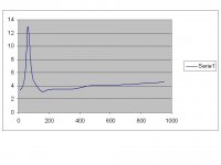
If you have a free air impedance plot of the woofer, please post it.
If you have a free air impedance plot of the woofer, please post it.
i have the plot, i made it using excell but i'm not so sure about its correctness, because the impedance at resonance is only 13 ohm. In order to make it i used a wien bridge oscillator where i adjusted two potenziometers to vary the frequency, in the output of the amplifier i connected a resistor of 173.6 ohm, measured with multimeter, and then the woofer, i took the voltage across the woofer for every frequency going from 10hz to 100hz with steps of 5hz and from 100hz to 1kHz with steps of 100Hz, then i inverted the formula for the resistor divider to find the impedance of the woofer. The voltage was measured with a common digital multimeter set to AC measures. Did i do right? because if i did wrong also the Qts is wrong.
How can i upload the plot?
How can i upload the plot?

- Status
- This old topic is closed. If you want to reopen this topic, contact a moderator using the "Report Post" button.
- Home
- Loudspeakers
- Multi-Way
- loudspeaker enclosure design