Hello all, I'm intrigued by this RCF horn sold to partner their already efficient midrange driver:
RCF Short horn/directivity device
RCF MR8N301 Driver
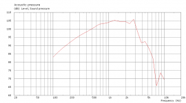
Looking at the datasheet, the response with the horn added actually gives greater efficiency toward the low end of the spectrum. This seems against typical horn theory where a horn would need to be relatively long to act on longer wavelengths? My first thought seeing the horn was that the driver already had a hump in its response from an undersized rear volume and that the horn just brought up the top end in line with this, but the opposite is seen.
So, what is really going on here? I've heard that it's more a directivity device than a conventional horn, which sounds logical, but the efficiency gain is substantial and worth taking advantage of, so how can we design one? I guess it can't be a waveguide as it features a phase plug.
Ultimately, I'd like to build such a device to fit to this inexpensive driver:
Ciare 6.38 MR3
but my efforts with hornresp have only produced results with unwieldly horns:


So, how would one design a device akin to the RCF one? Ideally, it'd be designed to attach with 2 drivers, similar to the arrangement seen here:
http://www.martin-audio.com/mla/f-acoustic-design/midrange-section.asp
Thanks for any input on this")
RCF Short horn/directivity device
RCF MR8N301 Driver
Looking at the datasheet, the response with the horn added actually gives greater efficiency toward the low end of the spectrum. This seems against typical horn theory where a horn would need to be relatively long to act on longer wavelengths? My first thought seeing the horn was that the driver already had a hump in its response from an undersized rear volume and that the horn just brought up the top end in line with this, but the opposite is seen.
So, what is really going on here? I've heard that it's more a directivity device than a conventional horn, which sounds logical, but the efficiency gain is substantial and worth taking advantage of, so how can we design one? I guess it can't be a waveguide as it features a phase plug.
Ultimately, I'd like to build such a device to fit to this inexpensive driver:
Ciare 6.38 MR3
but my efforts with hornresp have only produced results with unwieldly horns:
So, how would one design a device akin to the RCF one? Ideally, it'd be designed to attach with 2 drivers, similar to the arrangement seen here:
http://www.martin-audio.com/mla/f-acoustic-design/midrange-section.asp
Thanks for any input on this
i would concur with your comments on the 'usual' horn loading effect or goal. Also i would say you were more knowledgable than i. But i notice the Qts is quite high for a horn driver, i think. Also VC inductance is very high. Maybe these are a factor? The toroidal phase plug in the other link is interesting. I wonder if it would act as 2 concentric throats? The inner hole like a very small throat in behavior, allowing a higher cut off, and the concentric ring throat as a seperate throat or initial flare. Maybe im making zero sense? Lol. Id imagind the toothed baffle would spread the BW of the dual driver interferance, smoothing things and again allowing a higher BW limit.
If you look at the drivers mass corner 2*fs/Qt, this = 1.68kHz.
In a constant directivity device the frequency response starts dropping off at 6db./octave above this.
This driver however has a rise in output that starts about there and increases output at around 6db./octave to compensate, JBL has had a ten inch midrange driver with this characteristic for some time.
The phase plug is to reduce phase cancellation at the upper end.
rcw
Thanks for your responses! So we all believe this to be a directivity device rather than a conventional horn? Is it even possible to model this in HornResp? I'm guessing not, but perhaps Akakbak.
Yeah, the Martin Audio phase plug is a bit unique, I wouldn't necessarily try to copy that, building would be quite difficult I suspect. It is an interesting arrangement though and seems to perform well.
Ok, well the mass corner of the Ciare driver is:
302Hz x 2 = 604Hz/0.38 = 1.59kHz
But if we give the Ciare a suitable back volume the resonance of the driver in system is instead around 500Hz, which is how we should compare it to the sealed back RCF driver?
500Hz x 2 = 1000Hz/0.38 = 2.6kHz
So for successful use in a directivity device we want the Ciare to have a rising response above 2.6kHz? In fact it does a little bit, I think we could get useful response to 4kHz, with suitable attention paid to phase plugging. This is high enough assuming the response gets to 500Hz or so at the low end.
But I'm still quite unsure how a directivity device can be designed? Or how in fact it works, how are we getting gains at low frequencies from a horn of such minimal length? I can only assume since the directivity is being restricted that higher output is achieved within the newly defined, tighter, directivity pattern? But again, how can a 'horn' of such small dimensions have any effect on the lower frequencies at all?
Thanks again!
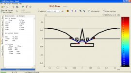
Axi driver can model this type of device quite well if you take into account that it is a program that only calculates around a cylindrical axis.
This is a short near field device that I described in this article....
Practical DIY Waveguides - Part 1
It has all of the basic features described here and can be seen as a two flare waveguide with constant directivity as described in this article.
rcw
This is a short near field device that I described in this article....
Practical DIY Waveguides - Part 1
It has all of the basic features described here and can be seen as a two flare waveguide with constant directivity as described in this article.
rcw
Thanks for your responses! So we all believe this to be a directivity device rather than a conventional horn?
No, it's a horn. Just a very short horn with a very high flare rate. Any time you put angled panels in front of a driver....it's pretty much a horn. The phase plug acts as a reduction in cross section area which smoothly tapers off as the horn flares. To get a rough start, you need to approximate the depth and area dimensions (area of mouth minus area of phase plug) for several cross sections and model it as a 4 segment conical horn.
Last edited:
If you model it as a conical horn until its final width dimension is around .7 of the mouth, and then put a circular arc that ends up at right angles to the baffle you just about have it.
This is pretty much the end section of the constant directivity horn first described by Keele, these have an exponential section before the conical one driven by a compression driver, this still the basic form used in things like the JBL bi radial horns.
The end flare removes the waist effect near lower cut off and reduces diffraction by removing impedance anomalies.
I have some Axi driver simulations of them and I will see if I can find them.
rcw
This is a similar device with no phase plug using a p. audio midrange driver...
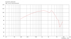
The frequency response is this....
When you use a phase plug....
The frequency response is this....
As you can see the plug increases the output up to 2kHz. and it falls of rapidly thereafter.
If you use a six inch driver and a smaller throat you might get usefull output to 5kHz.but the throat phse plug design starts to become complex
rcw
The frequency response is this....
When you use a phase plug....
The frequency response is this....
As you can see the plug increases the output up to 2kHz. and it falls of rapidly thereafter.
If you use a six inch driver and a smaller throat you might get usefull output to 5kHz.but the throat phse plug design starts to become complex
rcw
Attachments
Thanks for those examples! I got AxiDriver and VacsViewer yesterday but have only got as far as creating rough waveguide shapes. What I can't figure out is how you got those frequency response curves to show up in Vacs? It looks like you're using the demo too so it must be possible without needing the save feature. Once I have that I can have a go at creating something useful, though just like my HornResp use it'll be a bit uneducated and experimental
What I do is to enter the driver parameters and then make a word document, I found that you can cut and paste the baffle data directly, but have to manually enter the driver and vacs data.
I do not know how to model a rising driver frequency response, and since the program assumes a rigid cone or dome the decoupling effect that gives rise to it does not get modeled, apparently the effect is due to the undecoupled cone mass resonating with the voice coil inductance.
It is far from perfect but very good value for money, and it does accurately model the frequency response I measured for my article.
rcw
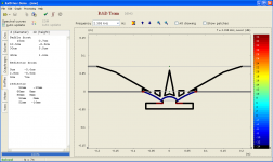
Well, I've had a go at entering the data and designing a useful horn. The cone geometry is mostly guesswork as the details aren't published, but I figure it'll be close enough.
I could only get response up to higher frequencies by using a more elaborate phasing plug and reduced throat area, as you suggested. Otherwise, response was found to be limited to only 2kHz.
This design seems to work up to 3.5kHz which is going the right direction, and appears to offer about 3dB gain. I am unsure if my phase plug is actually extending the upper response by creating more similar path lengths or if I've actually introduced some kind of 3kHz resonance which extends it artificially .
.
I can make the peak at 3kHz stronger, but what I'd like is to achieve a smoother response without that effective 'dip' at 2.3kHz or so. Also, is it possible to extract any more gain from a horn like this, would you expect to see more than an improvement of 102 to 105dB/1W/1m from such a horn? 3dB is still good mind, it's half the power requirements, but I've seen more gain from horns than this.
Additionally, what is the effect of adding a rear enclosure to the driver going to be? I can't see how to simulate that, if the software even can?
I could only get response up to higher frequencies by using a more elaborate phasing plug and reduced throat area, as you suggested. Otherwise, response was found to be limited to only 2kHz.
This design seems to work up to 3.5kHz which is going the right direction, and appears to offer about 3dB gain. I am unsure if my phase plug is actually extending the upper response by creating more similar path lengths or if I've actually introduced some kind of 3kHz resonance which extends it artificially
. I can make the peak at 3kHz stronger, but what I'd like is to achieve a smoother response without that effective 'dip' at 2.3kHz or so. Also, is it possible to extract any more gain from a horn like this, would you expect to see more than an improvement of 102 to 105dB/1W/1m from such a horn? 3dB is still good mind, it's half the power requirements, but I've seen more gain from horns than this.
Additionally, what is the effect of adding a rear enclosure to the driver going to be? I can't see how to simulate that, if the software even can?
Attachments
I haven't tried it but the software does have a baffle rear-reflector rear input that may well be able to simulate a rear enclosure.
In a conical horn I made I used a rear chamber that pushed the drivers resonance up to 300Hz. this has a Qt = 2, I removed this with the crossover.
The average efficiency increase was around 5db.
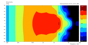
It is also instructive to do a directivity plot and I did this by using the normalise to y max command in vacs.
With the simulations I posted you get constant directivity starting from around 600Hz. and extending to 2kHz. with a 500mm. mouth., with the fancier phase plug and smaller throat it should extend higher than this.
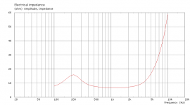
If you do the driver electrical impedance plot you should see any resonances as impedance anomalies, these short horns are usually fairly free of them.
rcw
In a conical horn I made I used a rear chamber that pushed the drivers resonance up to 300Hz. this has a Qt = 2, I removed this with the crossover.
The average efficiency increase was around 5db.
It is also instructive to do a directivity plot and I did this by using the normalise to y max command in vacs.
With the simulations I posted you get constant directivity starting from around 600Hz. and extending to 2kHz. with a 500mm. mouth., with the fancier phase plug and smaller throat it should extend higher than this.
If you do the driver electrical impedance plot you should see any resonances as impedance anomalies, these short horns are usually fairly free of them.
rcw
I tried to add a rear enclosure but it made the response completely ragged, I guess because there's no option to add stuffing to it like there is with HornResp. I hope in practise such an enclosure can be added with enough stuffing that it doesn't really affect the results seen from this simulation (ie, open back and enclosure stuffed with high absorbency at 500Hz+ are equal)?
I've had a look at impedance and directivity results. Also, while there I decided in practise this might be easier to build from bendy ply, and so I increased the smoothness of the contours. This had a pleasing effect on the response, limited to only 3kHz but smoother in the pass-band. A horn like this should sound well from 500Hz-3kHz? Perhaps over a wider range even.
Electrical impedance shows no anomalies that I can see so we should be resonance free. Directivity looks fairly constant over the pass-band, if I'm reading the graph correctly the horn has around 90-100 degree dispersion? In practise, it'd be good to have 90x60 or similar dispersion, which I guess involves making the horn flare less broad in the vertical axis? It might look a little like this:
http://www.diyaudio.com/forums/multi-way/151787-some-midrange-horns.html
Any suggestions for further refinement? It's probably going to be hard to get better than 105dB/1W/1m in the pass-band but extension of the response, particularly in the low end, would be welcome.
Thanks again!
Attachments
You can increase the output at the low end by using a suitable rear enclosure,
Smalls expression for sealed boxes is, Qt'/Qt = (1 + a)^.5, where Qt prime is the Qt you want and a = the compliance ratio, i.e. Vas/vb
from this you can calculate a rear enclosure to give you the low end you want.
Also keep in mind that the vertical directivity moves up in frequency as you decrease the angle, for instance a 500mm. wide mouth will have around 250mm. height for 90x40 and the lower directivity then goes up to 2kHz.. this is why you see two of these devices stacked vertically, to increase the vertical mouth dimension.
That's all I can think of for now, so good luck with it.
rcw
That's great if a rear enclosure could increase low end output by increasing the system Q. It'll have to be pretty tiny according to WinISD though, and I think getting a good amount of stuffing in there is important so we'll see how that goes.
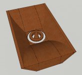
Here's a sketchup drawing of how the horn may be built. The side wall profiles match the Axidriver sim, the top and bottom panels are just angled, so hopefully this achieves a directivity pattern like 50x90 or similar (horn is 420mm x 230mm in this drawing).
The throat isn't exactly the same as the sim but I'm hoping this will be ok, the woodwork for this is already fairly advanced.
Attachments
The pastern is changed somewhat by the diffraction from the sharp vertical transition.
What I did in my horn is to use the minimum sized enclosure principle, this is a stainless steel pudding basin with rings and disks of particle board in it to reduce the volume and to make sure that no reflective path in it approaches any pass band frequency but are all above the upper crossover.
This is the scheme used in the cone compression drivers on the market, no stuffing is needed in this enclosure.
The alternative is to use the large absorbent filled enclosure, but getting the Qt high enough can be an issue because if the enclosure is rectilinear and too small you get rear reflections spoiling the frequency response.
I found that you can model this in axi driver by putting Qm and fs equal to what it might be if the driver has a natural Qt and fs of the one you need, and can achieve in the minimum box.
rcw
I see what you're saying about the rear enclosure, in fact it sounds like a sealed back driver is probably optimal for this but choices are too limited. We could add a close fitting pan over the driver rear like this though:
6" horn - Speakerplans.com Forums - Page 1
And fill in any large (with relation to 3kHz wavelengths!) areas as you did if necessary.
Is the transition area causing concern the one I highlighted? We can add putty or similar to these areas if that helps. I notice the RCF horn has these areas 'filled in'.
Attachments

Dam, I thought I was the only one to ever think of that. Any kitchen pot that is the right size will do it.
There is also something to be said for putting fillets in, some have them and some don't.
I would try both and see what the difference was, I suspect I would get lower diffraction near the throat and less likelihood of a diagonal standing wave.
rcw
There is also something to be said for putting fillets in, some have them and some don't.
I would try both and see what the difference was, I suspect I would get lower diffraction near the throat and less likelihood of a diagonal standing wave.
rcw
Marketing Hype vs Real Engineering
If you want horn performance, then design one using Hornresp. You are confusing marketing hyperbole with engineering fact. When horn dimensions are not comparable to the lowest frequency of interest, then it is not acoustically a horn at frequencies approaching that limit.
Regards.
WHG
Hello all, I'm intrigued by this RCF horn sold to partner their already efficient midrange driver:
RCF Short horn/directivity device
RCF MR8N301 Driver
Looking at the datasheet, the response with the horn added actually gives greater efficiency toward the low end of the spectrum. This seems against typical horn theory where a horn would need to be relatively long to act on longer wavelengths? My first thought seeing the horn was that the driver already had a hump in its response from an undersized rear volume and that the horn just brought up the top end in line with this, but the opposite is seen.
So, what is really going on here? I've heard that it's more a directivity device than a conventional horn, which sounds logical, but the efficiency gain is substantial and worth taking advantage of, so how can we design one? I guess it can't be a waveguide as it features a phase plug.
Ultimately, I'd like to build such a device to fit to this inexpensive driver:
Ciare 6.38 MR3
but my efforts with hornresp have only produced results with unwieldly horns:
So, how would one design a device akin to the RCF one? Ideally, it'd be designed to attach with 2 drivers, similar to the arrangement seen here:
MLA? Multi-cellular Loudspeaker Array. Martin Audio Ltd.
Thanks for any input on this
If you want horn performance, then design one using Hornresp. You are confusing marketing hyperbole with engineering fact. When horn dimensions are not comparable to the lowest frequency of interest, then it is not acoustically a horn at frequencies approaching that limit.
Regards.
WHG
I would certainly check the design with hornresp.
As I said in the waveguide article these devices can be seen as horns that work in the acoustic near field, defined as where r(2pif/c)=<1 .
In this region the imaginary part of the field predominates and at the value of 1 the real and imaginary are equal.
For a typical horn of this sort the field at the mouth starts to become predominantly real at around the lower cut off frequency and the imaginary region moves towards the throat as frequency increases. The place where the notional equivalent diaphragm is radiating from, (as Johansen says in the reference), moves towards the throat as frequency increases, and you can look at the reduction of the dimension of this notional diaphragm as giving the constant directivity property, as a piston that has linear reduction in diameter with frequency has constant directivity.
The primary goal of these devices is to control directivity and not to modify the acoustic impedance seen by the driver so in that sense they are not traditional horns but can also be called constant directivity baffles or ducts, and I am loath to use the much abused appellation, waveguides.
rcw
- Status
- This old topic is closed. If you want to reopen this topic, contact a moderator using the "Report Post" button.
- Home
- Loudspeakers
- Multi-Way
- Powerful midrange, RCF short horn, how does it work?