So far, no one (to my knowledge) has made a column similar to the SBH-10 using coax drivers and various height Paralines.Thanks for the comments ,I have some reading to do don't I!
Has anyone built anything like these,Like a diy layout? Pictures?Drawings.
Thanks,
NS
There are plenty of drawings of how to lay out Paralines, making a cabinet similar to the SBH-10 would not be any more difficult than making the Paraline PA I built.
That said, it would be a hell of a lot more work and expense than I'd want to put in to a relatively low output 160 x 10 degree column speaker
") .
.Attachments
Thanks for the comments ,I have some reading to do don't I!
Has anyone built anything like these,Like a diy layout? Pictures?Drawings.
Thanks,
NS
This is close, but doesn't use coaxes:
http://www.diyaudio.com/forums/multi-way/217298-square-pegs-33.html#post3191259
Hi Patrick,
thank for for your response. Unfortunately, it did not answer my question. The referenced Synergy patent recites in relevant part, p. 9, line 30 - p. 10, line 5 (emphasis supplied):
O.K. so the definition of local expansion rate is a distance over which the area increases by a constant, e.g., 2. Despite this rather peculiar definition, I can construct a plot of distance as a function of, e.g., constant increase of an area. This will happen every time that the difference between the distances is square root of the constant for a square-sided conical horn. So what?
However, given this definition of expansion rate, that you appear to have accepted by sending me to re-read the patent, I am still unsure, how to translate it to your presentation as frequency as a function of distance?
You tried to explain it in the following:
Could you please re-phrase your explanation, because I am not sure how I am supposed to calculate the flare rate, which according to you is the Synergy definition of "distance it takes for a small but readily measurable increase in area of the acoustic passageway (e.g. doubling of the acoustic passageway cross sectional area)" at every point (i.e., distance) as you wrote.
And no, I am not prepared to use Hornresponse, without understanding what I, and the Hornresponse, are doing.
Kindest regards,
M
thank for for your response. Unfortunately, it did not answer my question. The referenced Synergy patent recites in relevant part, p. 9, line 30 - p. 10, line 5 (emphasis supplied):
As used herein, the term "local expansion rate" refers to the distance it takes for a small but readily measurable increase in area of the acoustic passageway (e.g. doubling of the acoustic passageway crosss sectional area), starting at a point where the driver is tapped into the hom. Thus, the term "local expansion" bears reference to a small portion of the acoustic passageway as opposed to a reference to the expansion throughout the overall length of the horn.
O.K. so the definition of local expansion rate is a distance over which the area increases by a constant, e.g., 2. Despite this rather peculiar definition, I can construct a plot of distance as a function of, e.g., constant increase of an area. This will happen every time that the difference between the distances is square root of the constant for a square-sided conical horn. So what?
However, given this definition of expansion rate, that you appear to have accepted by sending me to re-read the patent, I am still unsure, how to translate it to your presentation as frequency as a function of distance?
You tried to explain it in the following:
The reason you can calculate the flare rate at any point along the throat is that a Unity or Synergy horn is basically a horn feeding a horn feeding a horn. Picture each segment as an independent horn that's stacked together.
So that's how you calculate the local flare rate. (Hornresp helps a lot - and JLH has documented how to do that in this thread.)
Could you please re-phrase your explanation, because I am not sure how I am supposed to calculate the flare rate, which according to you is the Synergy definition of "distance it takes for a small but readily measurable increase in area of the acoustic passageway (e.g. doubling of the acoustic passageway cross sectional area)" at every point (i.e., distance) as you wrote.
And no, I am not prepared to use Hornresponse, without understanding what I, and the Hornresponse, are doing.
Kindest regards,
M
Last edited:
front closure of the paraline is definately not expanding...
You could vary depth to maintain expansion, but you do
not want a wide exit slot, so you have to put up with it
being flawed...
A virtual curved front does help blend out the abrupt
change of flare (from none to whatever angle the face
is shaped to cover). The line array presents reflected
acoustic power back through the paraline to drivers,
all at same distance. The synergy array presents that
reflection at a multitude of distances, so better hidden
I would think?
The parabolic reflector is at a multitude of distances
even in the line array case, so no great problem there.
The reflection and transition from radial wave expansion
to plane wave non-expanding on journey to the merger.
I don't know if the cone sees radial expansion as the
compression driver would. since the cone surface
is uniformly distributed within the expansion, is that
section really expanding from the cone's perspective?
or not?
Last edited:
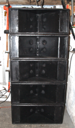
Assuming a 20mm wide Paraline exit in the SBH10, and an average of around 190mm height for each driver, each exit averages 3800 square millimeters, the cone area (Sd) is 7500 square millimeters.I don't know if the cone sees radial expansion as the compression driver would. since the cone surface is uniformly distributed within the expansion, is that
section really expanding from the cone's perspective?
or not?
The HF driver sees an expansion in area, the cone almost a 2/1 reduction in area at the Paraline exit.
The Paraline works for the HF end of the spectrum, the lower end is working pretty much like any 5 foot cone driver line array does.
Here's a dopey idea... for continuous expansion...
Suppose you make the return to center in two layers instead of one.
Each layer cut like a comb of flat trumpets. But the layers would be
staggered such that: Paraline reflectors would be continuously open
to the throats of at least one layer of flat trumpets or the other...
Keep it simple, it could be flat triangular trumpets... The mouth still
limits how much expansion is possible, but it could at least be made
to continuously expand. I don't know if that makes much difference.
Last edited:
To calculate the local area of expansion (the local flare rate) you look at the distance over which it takes to double the cross section area of the horn. Let’s say our mids tap into the horn where the area of the horn is 30cm^2. We then look to see how far down the horn it takes for the horn to expand to 60cm^2. For our example let’s use 6cm. Use Horn Response and enter 30 for S1. Enter 60 for S2, and 6 for L12. Hit “E” on your keyboard while you have the L12 field highlighted. This will make the horn contour Exponential. The flare rate will be displayed in the F12 field. In our example this should equal 316Hz.
Hi JLH,
thank you for the response. My English must be really poor, since it appears that I could not get my question across.
I do understand how you and Patrick Bateman are using Hornresponse to calculate the "local area of expansion (the local flare rate)" as you describe it.
However, I was trying to understand the concept of local flare rate a the application thereof to the driver loading. I have derived a relationship based on my assumption of what the Synergy patent is trying to disclose, but the resulting curves when overlaid on Patrick Bateman's curves, purportedly derived by your method from Hornresponse, did not agree. Hence my question regarding the underlying concept, to enable me to check my work.
However, yesterday I discovered Tom Danley's "A White Paper on Danley Sound Labs Tapped Horn and Synergy Horn Technologies", wherein Fig. 4 illustrates "Approximate driver loading of SH-50 based on where along the horn the driver is located". When I entered the parameters of SH-50, a square conical horn with 50 deg included angle, to my formula, and overlaid the resulting curve on Fig. 4, I have a match.
Based on the foregoing, I will now proceed under the false assumption that my understanding is correct. ;-)
Kindest regards,
M
Last edited:
If in doubt, read the patent
Short of reading the patent, the "instantaneous flare rate" would be the slope of the bounding curve? Or the second derivative? It has to be one or the other because higher order derivatives are not guaranteed to exist or be finite.
Stated in these terms, an OS waveguide has the lowest 2nd derivative given an initial slope of zero and a final slope of whatever the design angle is. Since the internal diffraction is proportional to the 2nd derivative, the OS has the lowest internal diffraction for the two given slope conditions.
Hi JLH,
thank you for the response. My English must be really poor, since it appears that I could not get my question across.
I do understand how you and Patrick Bateman are using Hornresponse to calculate the "local area of expansion (the local flare rate)" as you describe it.
However, I was trying to understand the concept of local flare rate a the application thereof to the driver loading. I have derived a relationship based on my assumption of what the Synergy patent is trying to disclose, but the resulting curves when overlaid on Patrick Bateman's curves, purportedly derived by your method from Hornresponse, did not agree. Hence my question regarding the underlying concept, to enable me to check my work.
However, yesterday I discovered Tom Danley's "A White Paper on Danley Sound Labs Tapped Horn and Synergy Horn Technologies", wherein Fig. 4 illustrates "Approximate driver loading of SH-50 based on where along the horn the driver is located". When I entered the parameters of SH-50, a square conical horn with 50 deg included angle, to my formula, and overlaid the resulting curve on Fig. 4, I have a match.
Based on the foregoing, I will now proceed under the false assumption that my understanding is correct. ;-)
Kindest regards,
M
Yes, the white paper does a good job of explaining how the conical horn has a variable flare rate as you move down the horn. The conical horn is not a fixed flare rate horn like the exponential, hyperbolic, tractrix, or LeCleach.
Really hard to phase plug a single driver to a line.
Paraline seems one of the few reasonable ways
to avoid crazy path contortions.
But when we synergy 2 drivers to appear from a
point source rather than a line, now each phase
plug delay is self asymmetrical. Maybe this allows
other (not flat) phase plug shapes to be carved?
I'm just saying it might be worth noodling.
Like maybe a slot over a 3inch speaker with a
triangular plate between, making a greater
delay at one end. To synergy in pairs of single
apparent source. Or maybe you guys could
storm up something a little more coherant?
We are also smearing the reflection of the slot
back to the driver, which might be a good thing.
Not all paths of one length to sudden expansion.
But curved delay for a curved wavefront.
Last edited:
Really hard to phase plug a single driver to a line.
Paraline seems one of the few reasonable ways
to avoid crazy path contortions.
But when we synergy 2 drivers to appear from a
point source rather than a line, now each phase
plug delay is self asymmetrical. Maybe this allows
other (not flat) phase plug shapes to be carved.
I'm just saying it might be worth noodling.
Like maybe a slot over a 3inch speaker with a
triangular plate between, making a greater
delay at the ends. Or maybe you guys could
storm up something a little more coherant?
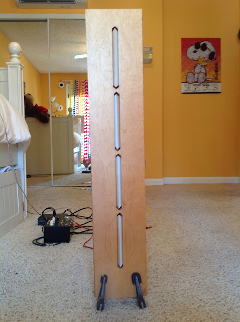
When I put a BG NEO 8 in a Paraline I noticed something odd -
The polar response *in* the Paraline was better than the polar response 'naked'.
I *did* lose some efficiency, but if good polars are a goal, there's some interesting possibilities.
Another thought I had was to do the Paraline in reverse:
A Paraline takes a circular wavefront, a compression driver, and it makes it ribbon shaped.
But there's nothing to stop you from going the other way:
Take a ribbon shaped diaphragm, and make it a circle.
^^ picture this with a ribbon at the exit instead of the entrance
This could allow some very interesting loudspeakers, such as a big Raven ribbon loading a circular waveguide.
The BG drivers are almost ideal though, because there's no cavity underneath the diaphragm, like there is in a ribbon.
Patrick, do you get the impression that a Paraline produces something strongly resembling a cylindrical wavefront? Does SPL drop off smoothly as one listens off-axis toward the top or bottom of the slot (allowing of course for some diffraction effects due to the slot needing to terminate in some manner) or is there the more usual interference and comb filtering that messes up the high end first? Does the wavefront emitting from a Paraline "want" to travel straight like a laser beam, from a perspective of vertical directivity? Or is it more like an infinite number of point sources that spray in all directions, with the vertical directivity arising from self-interference and lobing?
I do realize I'm asking a possibly complex question about sound propagation in not-very-precise language and sort of hoping your listening or your understanding of the theory hints at an answer. I'd appreciate any thoughts.
I do realize I'm asking a possibly complex question about sound propagation in not-very-precise language and sort of hoping your listening or your understanding of the theory hints at an answer. I'd appreciate any thoughts.
1) Not Patrick, but I have done a lot of Paraline measurements.1)Patrick, do you get the impression that a Paraline produces something strongly resembling a cylindrical wavefront?
2) Does SPL drop off smoothly as one listens off-axis toward the top or bottom of the slot (allowing of course for some diffraction effects due to the slot needing to terminate in some manner) or is there the more usual interference and comb filtering that messes up the high end first?
3)Does the wavefront emitting from a Paraline "want" to travel straight like a laser beam, from a perspective of vertical directivity? Or is it more like an infinite number of point sources that spray in all directions, with the vertical directivity arising from self-interference and lobing?
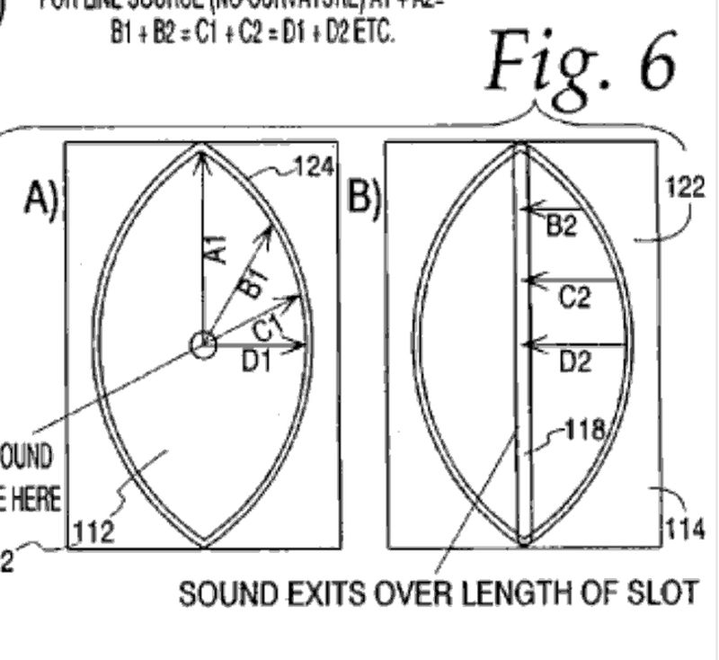
The wavefront at high frequencies resembles a portion of a cylinder.
2) A non divergent (equal path length from driver to exit center, top and bottom) Paraline has virtually no vertical beamwidth at VHF.
The actual vertical dispersion for a single 20 centimeter tall Paraline would be roughly 5 degrees at 16 kHz going to near 180 degrees below 1000 Hz.
3) The vertical directivity is a result of the Paraline equal path length resulting in a planar wavefront which diffracts horizontally, the horizontal dispersion controlled by the waveguide angle.
Patrick,When I put a BG NEO 8 in a Paraline I noticed something odd -
The polar response *in* the Paraline was better than the polar response 'naked'.
I *did* lose some efficiency, but if good polars are a goal, there's some interesting possibilities.
Another thought I had was to do the Paraline in reverse:
A Paraline takes a circular wavefront, a compression driver, and it makes it ribbon shaped.
But there's nothing to stop you from going the other way:
Take a ribbon shaped diaphragm, and make it a circle.
This could allow some very interesting loudspeakers, such as a big Raven ribbon loading a circular waveguide.
Other than being "interesting", what possible reason would you have to take a ribbon (which the Paraline emulates in polar response) and then convert it (with attendant losses and frequency response peaks and dips) to the radiation pattern of a compression driver that would do a far better job at driving a circular waveguide?
Your idea of "better polar response" is often at odds with what I find to be better, could you show the BG NEO 8 raw polar response compared to the Paraline?
Art
Patrick,
Other than being "interesting", what possible reason would you have to take a ribbon (which the Paraline emulates in polar response) and then convert it (with attendant losses and frequency response peaks and dips) to the radiation pattern of a compression driver that would do a far better job at driving a circular waveguide?[/img]
1) no one has done it
2) NEO8s and NEO3s sound great
3) The most compelling reason is space. I do a lot of car projects and there's a lot of situations where the sheer size of the driver becomes a problem. That was the thing that got me hooked on Paralines was the ability to turn sound 180 degrees or 360 degrees.
For the Synergy horns I'm building now I'm not using Paralines because I think that the Paraline is only useful in certain 'edge' cases.
Your idea of "better polar response" is often at odds with what I find to be better, could you show the BG NEO 8 raw polar response compared to the Paraline?
Art
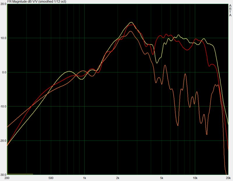
Here's the response of my NEO8s "bare". This is a special NEO8, only sold by GR Research, which is why the response looks different than what you see from PE.
On axis is yellow.
45 degrees off axis horizontally is red.
45 degrees off axis vertically is orange.
Note that the off axis drops like a rock, as illustrated by the orange line. This could be good or bad depending on your application, but it's clearly wildly asymmetric.
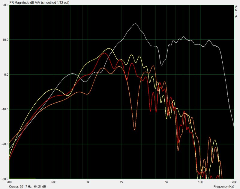
Here's the same driver, in a Paraline. On axis is yellow, 45 degrees off axis horizontally is red, 45 degrees off axis is orange, and the 'naked' response is grey. Note that the on-axis and the 45 degree off axis response 'tracks' each other closely. It's true that the Paraline is wiping out a lot of output above 5khz. At 10khz, the Paraline is down by 20 decibels.
One thing that kinda sucks about my measurements is that the Paraline "sounds" louder but the measurements show that the "raw" NEO8 is louder. I'm not sure what the story is there, it's possible that I may have adjusted the levels at one point. It doesn't make sense to me why the Paraline shows lower in the SPL output compared to the raw NEO8.
Makes sense to me, you ruined the forward response by putting the Paraline in front of a dipole ribbon (about the same thing as putting a folded towel in front of it), which makes the rear louder.One thing that kinda sucks about my measurements is that the Paraline "sounds" louder but the measurements show that the "raw" NEO8 is louder. I'm not sure what the story is there, it's possible that I may have adjusted the levels at one point. It doesn't make sense to me why the Paraline shows lower in the SPL output compared to the raw NEO8.
The response of that driver looks Monster Massive terrible
.Makes sense to me, you ruined the forward response by putting the Paraline in front of a dipole ribbon (about the same thing as putting a folded towel in front of it), which makes the rear louder.
The response of that driver looks Monster Massive terrible
the rear was sealed off. So Paraline in the front, sealed in the back.
- Home
- Loudspeakers
- Multi-Way
- Square Pegs