Nate,Here's the drawing.......clear as mud? I'm not one for fancy illustrations.
The .185 plate allows the CD to sit above the mid drivers' mounting flange, it's tight. I can take a pic if that doesn't make any sense.
As well as keeping out bugs, the bug screen keeps out small metal particles.
After seeing how much magnetic particulate is in all the dirt (and wind) around here, I would not think of cutting out a bug screen (which it looks like you would have to do to put the cone that far in to the throat), but all my compression drivers are used outdoors.
One thing that may slightly improve HF (in addition to Tom's suggestion of sealing all the pores with paint) is making the cone parabolic in shape.
The new version definitely looks better. Are there still a couple of minor "choke points" on the 45* angles where the flow reverses direction?
I take it the 4552 does not have the same style plug as the 4592?
Yeah, those "choke points" narrow to about .180". I may or may not take a look at that while I've got things apart.
The phase plug in the 4552 (and 4550 if I understand it correctly they use the same diaphragm assembly) doesn't extend to a long point like it does in the coax. You can see the sort of elongated half round at the top of my drawings.......that's an approximation of the phase plug in the 4552. I didn't include the slots that are in the back chamber that direct the wave to the phase plug.
Art, my Paralines are lined with open cell foam so I'm not worried about anything getting in the driver. Good point though.
Also, while you can make one that works as intended, I would not start that project until you have a good handle on how not to have pattern flip. The more asymmetric you make the pattern, the more problematic this unappreciated problem becomes.
If you have ever seen an old EV t-35 mounted “the wrong way” (up and down), that is the right way, based on how that horn actually radiates below 10KHz and that because of pattern flip.
Ugh, I really hadn't spent any time thinking about pattern flip.
An externally hosted image should be here but it was not working when we last tested it.
IMHO, it's the main reason it's almost impossible to get underdash horns to sound proper in a car. The vertical pattern 'flips' at 6khz, and you get an abrupt transition from narrow directivity to VERY wide vertical directivity. No matter how much time you spend trying to EQ it, it's nearly impossible to get it to sound right. Pattern flip is one of the main reasons I rarely bother with underdash horns, it's the reason that horns on the dash work pretty darn good (no pattern flip because the the waveguide blends into the dash and windshield) and pattern flip is just generally a p.i.t.a.
Good paper on it: Understanding Horn Directivity Control Synergetic Audio Concepts
Just thinking out loud here, with a vertical Paraline that's 10" tall we're going to get pattern flip at 1350hz. A couple days back I posted the CLF data that Tom's engineer measured from the VTC box. In the CLF data, we see the pattern flip; basically it goes from narrow vertical directivity up high, to broad directivity in the span of a single octave:
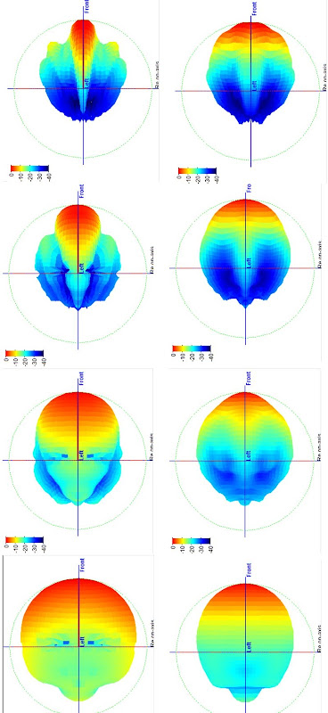
I am too lazy to look up my own post, but IIRC, in the pic above we have the vertical coverage of a VTC with a Paraline that's about 10" tall*. On the right is an SH-50. In the SH-50 measurements, we see that the directivity is fairly constant with frequency. In the VTC, we see it 'flip', as it goes from very narrow to very broad over the span of a few octaves. The frequencies measured are 4000hz, 2000hz, 1000hz, 500hz. (from top to bottom in the pic.) If the VTC has a 10" Paraline, flip will occur around 1350hz.
In an array, the behavior of the VTC is A Good Thing, but when used as a single unit, the individual box may likely exhibit the 'wonky' behavior that I hear in cars with underdash horns. To my ears, car horns sound like they need EQ, but EQ won't fix it, it's a directivity problem.
* all of that data is off the top of my head, so someone should fact check what I said before jumping to any conclusions
")
Patrick,
Your observations about patten flip in under dash horns is interesting. I never had this problem as I used horns mounted in the rear deck and used the rear glass as a deflector to bounce a symmetrical horn lens pattern towards the front of the car. I used no front speakers and only had a single source at the rear of the car. It took a little while to get used to sound coming from behind but soon it sounded normal to me.
Your observations about patten flip in under dash horns is interesting. I never had this problem as I used horns mounted in the rear deck and used the rear glass as a deflector to bounce a symmetrical horn lens pattern towards the front of the car. I used no front speakers and only had a single source at the rear of the car. It took a little while to get used to sound coming from behind but soon it sounded normal to me.
As noted in my last post, I hadn't spent any time thinking about pattern flip.
And I *do* believe that pattern flip sounds pretty obnoxious. Having listened to crazy-asymmetric horns in cars for most of my adult life, I'm very familiar with this type of distortion.
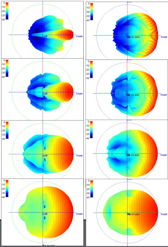
I was looking at the VTC data on the EL210, and pattern flip happens in the octave between 1000 and 500hz. (In the pic above, I've shown the vertical and horizontal directivity of the EL210. VD is the 1st column, HD is the 2nd column. Frequencies are 4khz, 2khz, 1khz, 0.5khz, from top to bottom.)
Seems like a pretty solid design; VTC has 'pushed' the frequency of pattern flip below the critical midrange. The frequency will go lower when you array it, as it was designed.
So - here's the idea I had:

What about a horn that's LeCleach in the vertical dimension, and conical in the horizontal dimension?
As I see it, this profile would offer the following advantages:
1) The main advantage of LeCleach is that the narrower angle at the throat will raise the SPL at the xover point, likely by 5-10dB. I posted sims on the SH-25 that shows that narrowing the throat boosts output significantly.
2) The problem with LeCleach is that the area of the throat is too small for our mids. But we can address that by using a conical profile for the horizontal coverage. Basically you get even coverage as you move left to right across the listening window, like in a conical horn. But the vertical coverage would be 'concentrated' into a narrower beam.
Another way to achieve the same goal would be to use a conical horn that's wide in one angle and narrow in the other. For instance, 90 degrees wide by 45 degrees tall. But the great thing about the LeCleach is that pattern flip is going to happen reallllllllllly sloooooooooowly.
Basically we don't have this abrupt transition from 25 degrees of radiation to 180 degrees of radiation. It still happens, but it happens soooooooo sloooooooowly.
Which I think would sound better.
Plus it would look cool.
Plus no one has ever done this before.
Thoughts?
If this is a stupid idea I could simply build a box that looks like a VTC EL210 but 4' tall. A mouth that tall would knock the directivity down another octave in the vertical plane.
And I *do* believe that pattern flip sounds pretty obnoxious. Having listened to crazy-asymmetric horns in cars for most of my adult life, I'm very familiar with this type of distortion.
I was looking at the VTC data on the EL210, and pattern flip happens in the octave between 1000 and 500hz. (In the pic above, I've shown the vertical and horizontal directivity of the EL210. VD is the 1st column, HD is the 2nd column. Frequencies are 4khz, 2khz, 1khz, 0.5khz, from top to bottom.)
Seems like a pretty solid design; VTC has 'pushed' the frequency of pattern flip below the critical midrange. The frequency will go lower when you array it, as it was designed.
So - here's the idea I had:
What about a horn that's LeCleach in the vertical dimension, and conical in the horizontal dimension?
As I see it, this profile would offer the following advantages:
1) The main advantage of LeCleach is that the narrower angle at the throat will raise the SPL at the xover point, likely by 5-10dB. I posted sims on the SH-25 that shows that narrowing the throat boosts output significantly.
2) The problem with LeCleach is that the area of the throat is too small for our mids. But we can address that by using a conical profile for the horizontal coverage. Basically you get even coverage as you move left to right across the listening window, like in a conical horn. But the vertical coverage would be 'concentrated' into a narrower beam.
Another way to achieve the same goal would be to use a conical horn that's wide in one angle and narrow in the other. For instance, 90 degrees wide by 45 degrees tall. But the great thing about the LeCleach is that pattern flip is going to happen reallllllllllly sloooooooooowly.
Basically we don't have this abrupt transition from 25 degrees of radiation to 180 degrees of radiation. It still happens, but it happens soooooooo sloooooooowly.
Which I think would sound better.
Plus it would look cool.
Plus no one has ever done this before.
Thoughts?
If this is a stupid idea I could simply build a box that looks like a VTC EL210 but 4' tall. A mouth that tall would knock the directivity down another octave in the vertical plane.
It probably will to you, probably not to othersWhich I think would sound better.
Plus it would look cool.
Truely the main factor in most horn designs
Not much has not been tried before - very little survives the "its new" marketing stage however.Plus no one has ever done this before.
Thoughts?
Why does everyone do the problem backwards? "This is what I have, how does it work?"
Wouldn't it make the most sense to say - "This is the polar response that I want, what shape will get me there?"
Interestingly enough there was an excellent (for reasons that we shall soon see) thesis done in Australia where the guy asked this exact question and then used a complex numerical code to find the waveguide shape that yielded his desired response. Low and behold! What do you think that he found? The shape was almost indistiguishable from an OS waveguide. What a coincidence!! I've seen that shape before!
Last edited:
It probably will to you, probably not to others
Truely the main factor in most horn designs
Not much has not been tried before - very little survives the "its new" marketing stage.
Why does everyone do the problem backwards? "This is what I have, how does it work?"
Wouldn't it make the most sense to say - "This is the polar response that I want, what shape will get me there?"
Interestingly enough there was an excellent (for reasons that we shall soon see) thesis done in Australia where the guy asked this exact question and then used a complex numerical code to find the waveguide shape that yielded his desired response. Low and behold! What do you think that he found? The shape was almost indistiguishable from an OS waveguide. What a coincidence!! I've seen that shape before!

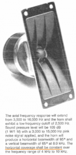
18 Sound XT1086
measurement of XT1086 with BMS compression driver
measurement of Gedlee Abbey, from your website
Oddly enough, I think I may save myself the hassle of making molds and just use an 18Sound XT1086. The 18Sound has the following advantages:
1) The main advantage is that the first ten centimeters of the horn is narrower than a conical or oblate spheroidal waveguide. Based on my sims, that should increase output at the xover point, enabling an easier transition from midrange to compression driver in a Unity horn. (Basically minimizing the trough between the two drivers.)
2) I already own a pair
3) The average coverage of the XT1086 is seventy degrees, which is an improvement over the 108x72 degree OS waveguide mold that I have. (Basically Unity horns seem to like narrow coverage angles, makes things a bit easier.)
The hybrid LeCleach that I posted a couple days ago might work a LITTLE bit better, but the XT1086 is pretty darn close. And did I mention that I already have a pair?
I thought pattern flip was also dependent on the distance away from the speaker.
One way of looking at it would be that pattern flip WON'T occur if you're seated within a certain angle of the loudspeaker. Basically, if you're right in front of it, pattern flip will occur at an angle that's outside of where you're seated.
But that's no good for people that listen off axis, like I do.
Plus, the power response of a horn with a bad case of pattern flip will be ugly.
I've never heard Mark Eldridge's Four Runner, but perhaps that's one of the reasons that he was so aggressive about treating the interior. (I recall that the area *behind* the listener was heavily treated.) Underdash car audio horns suffer from pattern flip in a big way, so Eldridge's strategy may have minimized the contribution of the 'room' to the power response.
Hi Guys
So far as horn “pattern flip”, there isn’t a great deal written about it as it is a flaw or wart which is nearly unavoidable and not a “selling feature”.
An examination begins with Don Keele’s realization that the horn wall angle and dimension govern where (what frequency) it will lose pattern control. Also, the Horizontal and Vertical angles interact through this handy thumb rule relationship.
http://www.xlrtechs.com/dbkeele.com/PDF/Keele (1975-05 AES Preprint) - Whats So Sacred Exp Horns.pdf
The upshot is that for a given straight walled horn (makes it easy to define the horn wall angle), if you make it half the angle, it will lose pattern control an octave higher.
That second angle is needed to avoid the narrowing he mentions as the frequency falls and you approach the pattern loss point.
What is less clear is that if one makes a simple horn, one is limited to a symmetric case unless one accepts pattern flip.
When the loudspeakers go places where you count on a radiation pattern shape, pattern flip is bad JuJu.
It is absolutely ludicrous in commercial sound that loudspeakers are given a pattern angle, which may only be achieved at one Frequency over it’s entire band (similar to how some rate sensitivity too).
The problem is clear when you do the math. What if you want a 20 degree by 80 degree horn?
No problem, you make a rectangular pyramid shape horn. This gives you the familiar wide short horn shape. Do the math though and one finds if you want to avoid pattern flip, the mouth height has to be 4 times the width while the real thing is more like the opposite of that, wide and short.
The problem is that if you loose pattern control in one plane, the control in the other plane pushes the energy into the uncontrolled direction. When in the flipped domain, the pattern will be narrow horizontally and wide vertically, even though the horn shape looks like it would do the opposite.
I have tried to avoid geometry which causes this problem but there are times when the package size and arrangement requires a compromise. For me, I more or less limit the asymmetry to around 1.6:1 because greater amounts produce much more severe pattern flip.
I said this is not a selling feature but a wart and while ubiquitous, is rarely discussed because of the problem fixing it.
You can see what a mild case looks like if you look at the clf file for an sh-95. This is a simple asymmetric horn which had to be small.
Open the CLF file, grab the radiation balloon with the cursor and swing it around and examine it on axis, pointed at you.
Notice up high, it is rectangular where the horn is large enough to set that pattern.
Now, step the frequency down from 1.6Khz and watch the shape change as it losses pattern control. Note that at 500-600Hz, the pattern is “flipped”.
Now, while this is a mild case, it can be very severe depending on the horn asymmetry. It is why the proper mounting for a T-35 horn is up and down if you want wide dispersion horizontally, it’s pattern flip begins 8-10Khz.
Hey Earl,
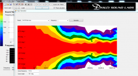
Sebastian has taken the first quick pass converting the spherical polar data to a + - 90 degree map style display.
I am asking him to see if he can get the raw data out of the CLF file because this has 1/3 octave averaging / smoothing and I would like to see less. Also, we don’t need the display to the low corner, the directivity down to 100Hz would be plenty. This is a 3dB step each color.
I haven’t looked at that many of this spectrogram style “maps” but to me it looks like it has a decent amount of directivity.
Best,
Tom
So far as horn “pattern flip”, there isn’t a great deal written about it as it is a flaw or wart which is nearly unavoidable and not a “selling feature”.
An examination begins with Don Keele’s realization that the horn wall angle and dimension govern where (what frequency) it will lose pattern control. Also, the Horizontal and Vertical angles interact through this handy thumb rule relationship.
http://www.xlrtechs.com/dbkeele.com/PDF/Keele (1975-05 AES Preprint) - Whats So Sacred Exp Horns.pdf
The upshot is that for a given straight walled horn (makes it easy to define the horn wall angle), if you make it half the angle, it will lose pattern control an octave higher.
That second angle is needed to avoid the narrowing he mentions as the frequency falls and you approach the pattern loss point.
What is less clear is that if one makes a simple horn, one is limited to a symmetric case unless one accepts pattern flip.
When the loudspeakers go places where you count on a radiation pattern shape, pattern flip is bad JuJu.
It is absolutely ludicrous in commercial sound that loudspeakers are given a pattern angle, which may only be achieved at one Frequency over it’s entire band (similar to how some rate sensitivity too).
The problem is clear when you do the math. What if you want a 20 degree by 80 degree horn?
No problem, you make a rectangular pyramid shape horn. This gives you the familiar wide short horn shape. Do the math though and one finds if you want to avoid pattern flip, the mouth height has to be 4 times the width while the real thing is more like the opposite of that, wide and short.
The problem is that if you loose pattern control in one plane, the control in the other plane pushes the energy into the uncontrolled direction. When in the flipped domain, the pattern will be narrow horizontally and wide vertically, even though the horn shape looks like it would do the opposite.
I have tried to avoid geometry which causes this problem but there are times when the package size and arrangement requires a compromise. For me, I more or less limit the asymmetry to around 1.6:1 because greater amounts produce much more severe pattern flip.
I said this is not a selling feature but a wart and while ubiquitous, is rarely discussed because of the problem fixing it.
You can see what a mild case looks like if you look at the clf file for an sh-95. This is a simple asymmetric horn which had to be small.
Open the CLF file, grab the radiation balloon with the cursor and swing it around and examine it on axis, pointed at you.
Notice up high, it is rectangular where the horn is large enough to set that pattern.
Now, step the frequency down from 1.6Khz and watch the shape change as it losses pattern control. Note that at 500-600Hz, the pattern is “flipped”.
Now, while this is a mild case, it can be very severe depending on the horn asymmetry. It is why the proper mounting for a T-35 horn is up and down if you want wide dispersion horizontally, it’s pattern flip begins 8-10Khz.
Hey Earl,
Sebastian has taken the first quick pass converting the spherical polar data to a + - 90 degree map style display.
I am asking him to see if he can get the raw data out of the CLF file because this has 1/3 octave averaging / smoothing and I would like to see less. Also, we don’t need the display to the low corner, the directivity down to 100Hz would be plenty. This is a 3dB step each color.
I haven’t looked at that many of this spectrogram style “maps” but to me it looks like it has a decent amount of directivity.
Best,
Tom
Attachments
Hi Tom
What you talk about is precisely why I resist using exponential waveguides in my designs despite the fact that some have been strongly critical of round and claim that elliptical would be better. My analysis says otherwise for precisely the reasons that you state. How sound radiation really works and how people think that it sould work are often quite different things.
Your map is a start, but 1/3 octave smoothing is way too broad. Everything will look great done that way. I use only a minimal smoothing, about 1/20th octave (but I use critical band smoothing that varies with frequency.) Also there are better ways to deal with the polar aspects than just interpolation, which has inherent errors. If you look at my data you will see that I have 2 degree resolution in angle and 1/20th octave in frequency. This is very high resolution and takes some doing to achieve.
Hopefully by Sunday I'll have both Paralines modified to have a reflector running nearly to the phase plug, following the driver exit angle and beginning the 1/4" internal height in the comp driver itself. It's going to be difficult to get the driver lined up over the reflector properly..... We'll see. If I have to I'll pull the back chamber/diaphragm assembly and mount the magnets first so I can see down the throat. I've got a cad drawing I'll post up later today showing what I'm up to.
So I'm not lazy and did actually do this. The driver mounting plate smoothly transitions to the CD throat angle, with the Paraline reflector continuing up into the CD like in my drawing. I wasn't very scientific about this process and made several changes all at once. I added a 45° chamfer on the "eye" layer to better match the outside eye 45° chamfers like Paul W noticed and keep the inside height from pinching down to less than .2". There were a few slight mismatches in the layers at the bend that I smoothed over, using a file and Danley's tip about sealing the Paraline. I sealed it with paint and wood glue.
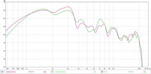
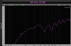
I must admit that while I was hoping for improvement, I wasn't sure how it would result. Here's an on axis measurement pre- and post modification. Measured on different days but with the mic at the same height and distance from the exit reflector of the Paraline. Nevermind the levels on the graph, and I did offset one so they would line up since I don't keep track of the levels I'm testing at. Purple is before the mod and green is after. Without any eq they're both pretty ugly and I can't say that from these measurements there was any improvement. Polar measurements did seem a bit more consistent but I can't see why that would be. Most likely just measurement conditions as I'm doing these in my living room and it isn't exactly large
.The other day I decided to go a step further and continue the CD throat reflector right up to the phase plug itself. This was pretty difficult work but I think it came out ok. Lots of trial and error! I measured with the horn on the stand and the mic in the same position before and after this mod and the result was negligible at best.
Attachments
Originally Posted by Tom Danley
Do the math though and one finds if you want to avoid pattern flip, the mouth height has to be 4 times the width while the real thing is more like the opposite of that, wide and short.
Not a lot of people know that, well they do now
Years ago Motorola used to recommend that their rectangular Piezo horns be mounted verically for correct dispersion. At the time it seemed odd, as no other horn manufacturer, i was aware of anyway, suggested this ? At least somebody @ Motorola knew their onions, & that was over 30 years ago
I guess because Piezos got a bad name, due to most people directly wiring them to the Amp, instead of using a power resistor & Xover, as i did, they didn't give the mounting advice much creedence ? Or never read it as they ignored Piezos ?
I'm not saying Piezos are All that, but they do sound a Lot nicer Xover properly
The Motorola ones were the best of their type. When the patent ran out & copies appeared they wern't as good !The rectangular Motorola Piezo horn was very similar to the Electro-Voice T-35 tweeter horn, which had recommended vertical mounting decades before.Not a lot of people know that, well they do now
Years ago Motorola used to recommend that their rectangular Piezo horns be mounted verically for correct dispersion. At the time it seemed odd, as no other horn manufacturer, i was aware of anyway, suggested this ? At least somebody @ Motorola knew their onions, & that was over 30 years ago
Pattern flip is not a new concept, but without measurement is "hard to get".
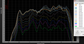
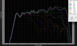
Below are an equalized 90 degree horizontal "non divergent" Paraline, the horizontal dispersion shows very uniform (excellent) pattern control to below 500 Hz.
The vertical control goes from about 16 dB down at 16K 30 degrees off to only about 1dB down at 500 Hz, from a narrow beam to a nearly omnidirectional radiation pattern.
Art
Attachments
So - here's the idea I had:
What about a horn that's LeCleach in the vertical dimension, and conical in the horizontal dimension?
Plus it would look cool.
Plus no one has ever done this before.
Thoughts?
If this is a stupid idea I could simply build a box that looks like a VTC EL210 but 4' tall. A mouth that tall would knock the directivity down another octave in the vertical plane.
Hello Patrick,
I used to study a horn having a better control directivity in the horizontal plane than the axisymetriacl Le Cléac'h horn while maintaining the most acoustical resistive load to the driver on most of its useful frequency range.
Here is the result:
Too bad no one built it since today...
Best regards from Paris, France
Jean-Michel Le Cléac'h
Attachments
Originally Posted by weltersys
The rectangular Motorola Piezo horn was very similar to the Electro-Voice T-35 tweeter horn, which had recommended vertical mounting decades before.
Ahh, the T-35, i remember it, but didn't realise about the mounting details. See my screnie for the V/H beamwidth, which "seem" very close. I found a www with a number of other similar EV horns http://hf-antenna.com/Flotsam/EV/How_to-build_a-EV-spkr_system.pdf
Pattern flip is not a new concept, but without measurement is "hard to get".
Apparently, not new, but not well known. But it might improve from now on
@ Jmmlc
Stunning designs & concept
Too bad no one built it since today...
I recently discovered the iwata range, which are based on yours Horns
Apart from the other benefits, what "appears" incredible to me, is the "apparently" seemingly shorter lengths, compared to other horns, but inspite of that, go down lower !
Attachments
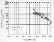
The T-35 horizontal dispersion goes from 110 degrees at 3kHz to 85 at 10kHz, a 25 degree range, the horizontal from 160 to 60, a 100 degree range. That "seems" a rather large difference to me.Ahh, the T-35, i remember it, but didn't realise about the mounting details. See my screnie for the V/H beamwidth, which "seem" very close.
@ Jmmlc
Stunning designs & concept!
I recently discovered the iwata range, which are based on yours Horns
Apart from the other benefits, what "appears" incredible to me, is the "apparently" seemingly shorter lengths, compared to other horns, but inspite of that, go down lower !
As far as the Iwata horns, if one is not concerned with constant directivity, a relatively low cutoff is not hard to achieve.
The Paraline which I posted polars for in post 496 has usable response down to 167 Hz (EV DH1AMT driver), and is only about 11.5 inches (29 centimeters) in length. It holds a uniform in horizontal response of 90 degrees from 500 -16 kHz, the much longer Iwata 300 goes from about 100 degrees to 15 degrees over the same range.
Art
Attachments
Last edited:
... Here is the result:
Too bad no one built it since today...
Wow. That would make a bold design statement if painted to resemble a pair of lips.
- Home
- Loudspeakers
- Multi-Way
- Square Pegs