Hi Earl, all
I would be tempted to describe the Paraline as something between a lens and a horn. So far as time of flight, It is a path length equalizer that has some adjust-ability in several ways. The pictures on the Yorkville website are the best illustrations I can point to as to what is inside.
Actually they don’t do the real item much justice, they are very nicely made.
Also, while it might seem unlikely, some of the Paralines are as smooth or smoother than the response of some normal horns.
The reason is that the space between the two plates where the sound exits the driver, is acoustically too small to support reflections between them. If the space was say ¼ wl or less at the highest F in question, you can picture how reflections between the two would not exist in any significance. If / while the source size is small enough, it cannot radiate anything but a simple expanding radial radiation between the two plates.
When the difference between the inner and outer path is less than ¼ wl, sound can travel around a bend like a fluid, just like it has to within the compression driver. If one does not introduce a sudden change in area, sound can travel around such a bend with the ease of a fluid, without a significant discontinuity. Now, I would not be truthful if I didn’t say there were a few other details which come to play, for example if you make one out of wood one will lose dB’s up high if the wood pores are not well sealed. On the other hand, if you build, measure, alter and repeat, even homemade versions can be very usable.
What is not obvious is that by changing the shape of the eye slot, one can adjust the curvature of the exit wavefront (time of flight), if the eye is made narrower relative to height, one makes a diverging pattern etc.
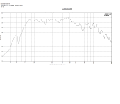
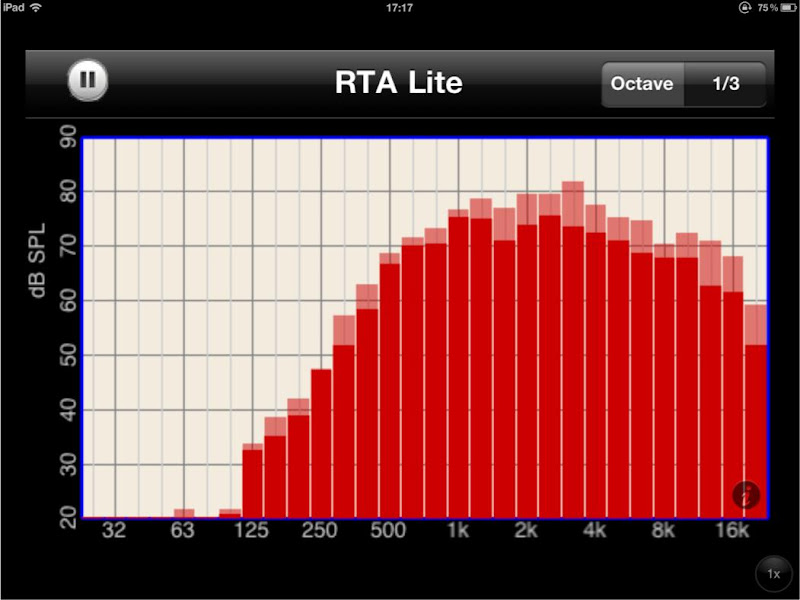
Here is a screen shot of a Paraline prototype I was working on a couple years ago. This is a large one (60 inches tall) that has a ring of mid drivers around the compression driver. Shown here is the hf only, no eq or crossover, raw in room response.
Since the size governs the pattern loss frequency, one use is a very directional but not especially high output speaker.
For the same size, these Paraline horns radiate MUCH less energy to the rear and sides than “an array of sources” which is a good thing in commercial sound.
The focus at work though has been at the other end, very powerful single source speakers and that has been driving the bus. These use a combiner, sort of an offshoot of the Paraline and I am really pleased how these are working out. These speakers are very different sounding, much more hifi so it’s fun to do side by side demos with the big name concert style systems they replace or go up against. If you go to see the Spartans by you or back to Penn State you will get a chance to hear the latest versions of the Synergy horns. The system going in at LSU will be the most powerful sound system ever installed in a stadium which should be fun this Fall.
Best,
Tom
I would be tempted to describe the Paraline as something between a lens and a horn. So far as time of flight, It is a path length equalizer that has some adjust-ability in several ways. The pictures on the Yorkville website are the best illustrations I can point to as to what is inside.
Actually they don’t do the real item much justice, they are very nicely made.
Also, while it might seem unlikely, some of the Paralines are as smooth or smoother than the response of some normal horns.
The reason is that the space between the two plates where the sound exits the driver, is acoustically too small to support reflections between them. If the space was say ¼ wl or less at the highest F in question, you can picture how reflections between the two would not exist in any significance. If / while the source size is small enough, it cannot radiate anything but a simple expanding radial radiation between the two plates.
When the difference between the inner and outer path is less than ¼ wl, sound can travel around a bend like a fluid, just like it has to within the compression driver. If one does not introduce a sudden change in area, sound can travel around such a bend with the ease of a fluid, without a significant discontinuity. Now, I would not be truthful if I didn’t say there were a few other details which come to play, for example if you make one out of wood one will lose dB’s up high if the wood pores are not well sealed. On the other hand, if you build, measure, alter and repeat, even homemade versions can be very usable.
What is not obvious is that by changing the shape of the eye slot, one can adjust the curvature of the exit wavefront (time of flight), if the eye is made narrower relative to height, one makes a diverging pattern etc.
Here is a screen shot of a Paraline prototype I was working on a couple years ago. This is a large one (60 inches tall) that has a ring of mid drivers around the compression driver. Shown here is the hf only, no eq or crossover, raw in room response.
Since the size governs the pattern loss frequency, one use is a very directional but not especially high output speaker.
For the same size, these Paraline horns radiate MUCH less energy to the rear and sides than “an array of sources” which is a good thing in commercial sound.
The focus at work though has been at the other end, very powerful single source speakers and that has been driving the bus. These use a combiner, sort of an offshoot of the Paraline and I am really pleased how these are working out. These speakers are very different sounding, much more hifi so it’s fun to do side by side demos with the big name concert style systems they replace or go up against. If you go to see the Spartans by you or back to Penn State you will get a chance to hear the latest versions of the Synergy horns. The system going in at LSU will be the most powerful sound system ever installed in a stadium which should be fun this Fall.
Best,
Tom
Attachments
I reused existing PA cabinet shells when building my Paralines, I was concerned that having parallel top and bottom horn walls might cause a standing wave problem.
To my surprise, angling the top or bottom walls on the prototype made no measurable difference in on axis response, in fact removing the top and bottom made no difference either!
When I saw (and heard) that attribute of the Paraline, I knew that it was doing something I had not experienced before.
The Paraline is very good for the desired application of multiple drivers on a single horn, or narrow vertical dispersion in a line array, but the ragged frequency response it imparts is a trade off that makes it a poor choice for home use.
Art

IMHO, the Paraline has the potential to deliver smooth 'hifi' output. In order to do this, we need to satisfy two requirements:
1) The horn must be of sufficient size
2) The horn must be carefully built
Here are the reasons I believe this:
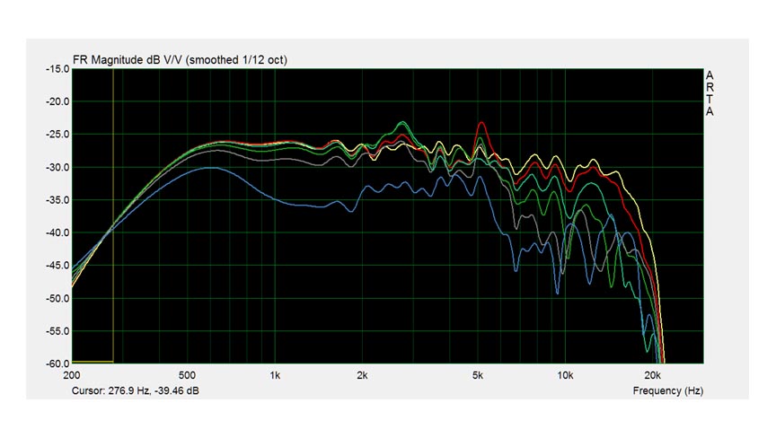
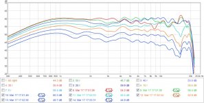
In the pics above, I've shown measurements of five different Paralines.*
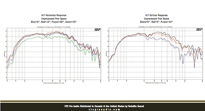
In those measurements, I believe that we see a trend. The Paralines which use small diaphragms and careful construction measure the smoothest. For instance, the VTC Paraline (measurement two) is relatively smooth. My 'Stargate' Paraline (measurement five) is smoother than my earlier Paraline (measurement four.) Your Paraline with an EV DH1-AMT uses a diaphragm that's 7.62cm in diameter; my Paraline with a Celestion CDX1-1425 uses a diaphragm that's 3.6cm in diameter.
The Paraline from the fifth measurement was built using a template that I printed on my PC; the Paraline from the fourth measurement was 'eyeballed', I basically did it with a sharpie.
See how the fifth is so much smoother? Both use the same compression driver.
I believe the reason that we need a small diaphragm and a very carefully constructed Paraline is due to the wavelengths involved. For instance, an error of just 1.7cm at 5khz will make a measurable difference in the response. And when we build these things 'by eye', a lot of small errors can creep in.
The other reason for small drivers is because it smooths out the ripples in the output which are due to the impedance mismatch. The alternative would be to use a larger height inside of the Paraline, but that rolls off the highs, an unacceptable solution.
* Paraline 1 is Nate Hansen's, using dual mids and a dome tweet. Paraline 2 is the VTC EL210 w/BMS 4550. Paraline 3 is yours, using the 3" EV DH1-AMT. Paraline 4 is mine, with the Celestion CDX1-1425 and the PE $2 buyout mids. Paraline 5 is my 'stargate', basically half a Paraline with a Celestion CDX1-1425.
Patrick,In the pics above, I've shown measurements of five different Paralines.*
In those measurements, I believe that we see a trend. The Paralines which use small diaphragms and careful construction measure the smoothest.
See how the fifth is so much smoother? Both use the same compression driver.
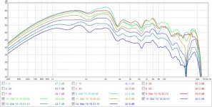
The primary "trend" I see in the measurements is those with a large vertical scale and more smoothing look smoother.
As you can easily see below, my 3 inch diaphragm Paraline "A" is much smoother than any of the other units tested
") .
.Art
Attachments
Last edited:
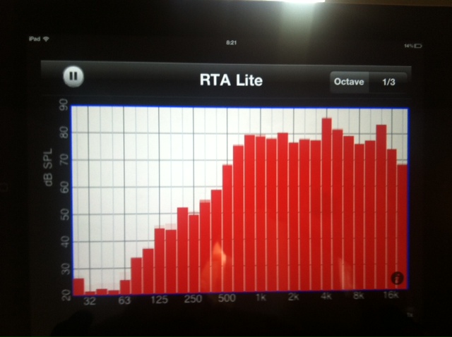
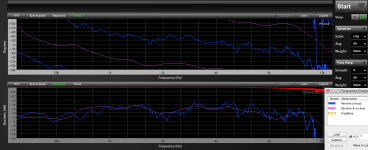
That measurement set of mine that PB posted was a very crude setup to get an idea if the thing was going to work. The dome tweet and sealed off 3" wideband drivers were mounted to a piece of cardboard with no reflector at the tweeter "throat" and eq'd profusely.
Here's a set with the Paraline mounted to a 60x40 conical horn measuring 20"w x 25"h. BMS 4552nd CD. 3ms gate measured at about 1.5-2 meters, 10° steps. No eq just a 40uf protection cap. Nevermind the dB scale it's not calibrated. The nicer looking set has been eq'd (obviously) and has 4 closed back Celestion mids flanking the BMS. This was my first time building horns, and I can tell you they are far from perfect. Prototypes really. Same can be said for the Paralines.
with no reflector at the tweeter "throat" and eq'd profusely.Here's a set with the Paraline mounted to a 60x40 conical horn measuring 20"w x 25"h. BMS 4552nd CD. 3ms gate measured at about 1.5-2 meters, 10° steps. No eq just a 40uf protection cap. Nevermind the dB scale it's not calibrated. The nicer looking set has been eq'd (obviously) and has 4 closed back Celestion mids flanking the BMS. This was my first time building horns, and I can tell you they are far from perfect. Prototypes really. Same can be said for the Paralines.
Attachments
I still think these have hifi potential. TD specifically states that the entire para line must be kept to less than 1/4 wavelength. Could the top end raggedness be due to these DIY paralines having a space at the CD's throat greater than 1/4wl? I think a throat insert that ensures the paraline "depth" is never exceeded even upon exit from the CDs phase plug. I'm not sure if I'm explaining myself very well.
Basically what I'm seeing is that even with the little cone section that faces the CD exit the spacing is already being allowed to expand to the CD exit's diameter before being constricted to the 1/4wl paraline passage. I'm guessisng this is basically acting as a throat chamber and causing the HF response anomalies.
So why not extend the paraline into the CD exit so that the wavefront never expands past the designated size? Well besides it being difficult to construct. Could this be what TD is telling us?
I apologize if this has already been covered. It has been a while since I last checked into this thread. Awesome work and a big thanks to TD for contributing to the thread.
I know exactly what you mean with the throat reflector. Going from nothing to a basic 45° that extended almost to the bug screen on the CD made a huge difference in the response. I chamfered the driver plate on the reflector side so it would fit nicely over the reflector and the 1/4" internal height begins as close to the CD as I could get it. If I was going to continue to optimize this design I'd do what you are suggesting......remove the bug screen and run the reflector up into the CD itself.
My goal is to have a "regular" 60x60 Synergy with these drivers built this year so I've been focusing on that. I don't see any reason (for myself) for a Paraline in my living room vs. a Synergy horn. That said, I'm a machinist (and a lathe guy at that) so turning up a nice CD reflector wouldn't be a huge deal. If this winter keeps dragging on like it is I might do just that.
My goal is to have a "regular" 60x60 Synergy with these drivers built this year so I've been focusing on that. I don't see any reason (for myself) for a Paraline in my living room vs. a Synergy horn. That said, I'm a machinist (and a lathe guy at that) so turning up a nice CD reflector wouldn't be a huge deal. If this winter keeps dragging on like it is I might do just that.
Member
Joined 2003
Because of the possibilities with vertical directivity, this device still intrigues me...but only if response can be made smooth acoustically. So, extending a reflector/director up over the exit cone in a BMS ring radiator seems like a really good idea.
Nate...what material did you use for your latest attempt? How thick and how smooth was the passageway?
Nate...what material did you use for your latest attempt? How thick and how smooth was the passageway?
Because of the possibilities with vertical directivity, this device still intrigues me...but only if response can be made smooth acoustically. So, extending a reflector/director up over the exit cone in a BMS ring radiator seems like a really good idea.
Nate...what material did you use for your latest attempt? How thick and how smooth was the passageway?
I had a response all typed up that linked to your latest center channel iteration that controls the vertical...then my browser crashed. I'll have to find it again. I'd like to build a sort of Synergy/Paraline hybrid that gives us broadband tightly controlled vertical directivity with fairly wide horizontal directivity...and no pattern flip. IMO that directivity would be ideal for a home setting, but not easy to pull off.
Here is the thread about Paul's new center channel that is a sort of mini-array: A new center channel for the Octagon
Pic:

I'm thinking a home version of a Danley J2 or J3. It seems those aim to achieve a similar goal.
Pic:
I'm thinking a home version of a Danley J2 or J3. It seems those aim to achieve a similar goal.
I know exactly what you mean with the throat reflector. Going from nothing to a basic 45° that extended almost to the bug screen on the CD made a huge difference in the response. I chamfered the driver plate on the reflector side so it would fit nicely over the reflector and the 1/4" internal height begins as close to the CD as I could get it. If I was going to continue to optimize this design I'd do what you are suggesting......remove the bug screen and run the reflector up into the CD itself.
My goal is to have a "regular" 60x60 Synergy with these drivers built this year so I've been focusing on that. I don't see any reason (for myself) for a Paraline in my living room vs. a Synergy horn. That said, I'm a machinist (and a lathe guy at that) so turning up a nice CD reflector wouldn't be a huge deal. If this winter keeps dragging on like it is I might do just that.
An externally hosted image should be here but it was not working when we last tested it.
Another option that's a bit easier and cheaper is to simply make a ring. Here's one way to do it:
1) Buy ten of these 1/2" Dome Tweeter Element 10 Pcs. 275-010 ($29.50 per channel)
2) Arrange them in a ring at the center of the Paraline
And that's about it!
The reason that this works is that the ideal shape for the entrance to the horn is a point or a ring. This is different than typical horns, because typical horns radiate in three dimensions. The Paraline only radiates in two*.
So you put these in a ring, and *voila*, no need for a compression driver.
It looks like ten of these would make a ring about 2.5" in diameter, so basically a similar shape as a BMS 4550. While ten of these are much much cheaper than a BMS, the main reason I'd use them instead of a BMS isn't the price; it's because they *don't* have a phase plug. (IE, I can't see a way to mount the BMS without it's phase plug; it's integral to the device.)
It *might* be possible to try the same stunt with a B&C DE25, DE250, Dayton D250P etc. Basically mount the compression driver dome-side-up into the Paraline. But my 'hunch' is that the high frequencies would be AWOL because radiation from one side of the dome would interfere with radiation from the other side. A 'ring' arrangement doesn't suffer from that problem.
avicenty built a Paraline with disc-shaped ribbon tweeters here:
http://www.diyaudio.com/forums/multi-way/217298-square-pegs-33.html#post3191259
The PE drivers are a similar idea, except with more displacement and the potential for a very low xover
Here is the thread about Paul's new center channel that is a sort of mini-array: A new center channel for the Octagon
Pic:
I'm thinking a home version of a Danley J2 or J3. It seems those aim to achieve a similar goal.
Danley Jericho has wide directivity; it wouldn't offer the narrow directivity that Paul is looking for.
Danley's designs put phase coherency at a high priority.
And though I'm a big cheerleader for the Paraline technology, they simply cannot be phase coherent at high frequencies. This is because of the distance from the top of the Paraline exit to the bottom of the Paraline exit.
For instance:
Let's say you have a Paraline with an exit that's 25cm tall by 1cm wide. And let's say you are seated 300cm from the Paraline. With a Paraline that size, the top of the Paraline will be 1.03cm 'out of sync' with the bottom of the Paraline. If we want to keep all our wavelengths within one quarter of each other, then this Paraline will not be phase-coherent above 8252hz.
Does that make sense?
Basically, the ideal radiator is a point, and as our radiator becomes more and more astigmatic, it's ability to be phase coherent gets lower and lower in frequency.
In the example above, our 'cutoff' where it can no longer be phase coherent will drop every time you add a Paraline. So one Paraline is phase coherent to 8252hz and four Paralines are potentially phase coherent below 2063hz.
And of course I said "potentially", because you have to satisfy a bunch of other requirements first
But, basically you can't get phase coherent with a Paraline above a certain frequency, and that frequency depends on the shape of the Paraline exit.
If you start looking at the maths, you'll notice that this is also a reason that the VTC is curved
Oh, if it wasn't clear from my last post, "A" is the height of the radiator, "b" is the distance to the listener on axis, and "c" is the distance to the listener from the top of the device. With a sphere we have the potential to be phase coherent, but the flat radiator can't be phase coherent at all frequencies. (it CAN be phase coherent BELOW a specific frequency.)
While a sphere is optimum, it's possible to get phase coherent with a flat diaphragm. The old Quads do that, and IMHO it's one of the reasons they sound so much different (and better) than conventional planars and ribbons. The Quad radiates from a series of rings, as shown above.
An externally hosted image should be here but it was not working when we last tested it.
While a sphere is optimum, it's possible to get phase coherent with a flat diaphragm. The old Quads do that, and IMHO it's one of the reasons they sound so much different (and better) than conventional planars and ribbons. The Quad radiates from a series of rings, as shown above.
Oh, if it wasn't clear from my last post, "A" is the height of the radiator, "b" is the distance to the listener on axis, and "c" is the distance to the listener from the top of the device. With a sphere we have the potential to be phase coherent, but the flat radiator can't be phase coherent at all frequencies. (it CAN be phase coherent BELOW a specific frequency.)
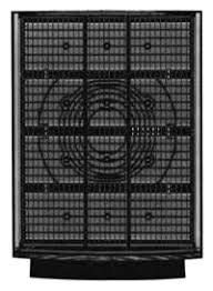
While a sphere is optimum, it's possible to get phase coherent with a flat diaphragm. The old Quads do that, and IMHO it's one of the reasons they sound so much different (and better) than conventional planars and ribbons. The Quad radiates from a series of rings, as shown above.
That's what Keele does with his CBT, bent backwards and shaded volume so it performs like part of a sphere.
That's what Keele does with his CBT, bent backwards and shaded volume so it performs like part of a sphere.
If anyone reading this thread wants to learn about how the Paraline works, read the CBT papers. As wesayso noted, there's a lot of common ground. (Don Keele is a horn guy going waaaaaaay back, of course, and the CBT is a technology that competes directly with the VTC boxes in the prosound world.)
I understand that, but a paraline that is 12.5cm tall should allow for coherent phase below 16khz. I'm not suggesting 4 long paralines.
I guess I've just been trying to find a good creative use for HiFi paralines.
How about reversing the paraline to take a line source and converge it to a point source. Something like a tall, narrow AMT converged to a circular point source exit. I'm trying to visualize what the wavefront would look like. I think it would be inverted spherical but like Danley said you can manipulate the wavefront with different exits. The advantage to putting a paraline in front of a rectangular AMT is that you would get the benefits of the large surface area AMT without the downside of its height and beaming above 8khz. maybe I'm not thinking of it in the right way.
I understand that, but a paraline that is 12.5cm tall should allow for coherent phase below 16khz. I'm not suggesting 4 long paralines.
Agreed. I just pointed out the phase problems with the Paraline because I think some people might be wondering why Danley doesn't use them in anything but the Genesis horns. I can't speak for him, but I'm guessing it's because the Layered Combiner can be phase coherent in three dimensions, while the Paraline can only be phase coherent in two. (Because the LC can generate a spherical wavefront, while the Paraline can only generate a flat or curved wavefront.)
I guess I've just been trying to find a good creative use for HiFi paralines.
How about reversing the paraline to take a line source and converge it to a point source. Something like a tall, narrow AMT converged to a circular point source exit. I'm trying to visualize what the wavefront would look like. I think it would be inverted spherical but like Danley said you can manipulate the wavefront with different exits. The advantage to putting a paraline in front of a rectangular AMT is that you would get the benefits of the large surface area AMT without the downside of its height and beaming above 8khz. maybe I'm not thinking of it in the right way.
I hate to be a downer, but the optimum shape at the entrance is a ring or a point. There really isn't a lot of room for error; if you diverge from the optimum shape by even one inch, you're going to see comb filtering.
Check out the Peavey paper on the 'Quadratic Throat Waveguide'; in the Peavey paper they showed that even something as basic as shaving a fraction of an inch off of the throat reduces distortion.
Again, I don't want to discourage anyone from experimentation
Just suggesting that based on my understanding how the device works, you want a point or a ring at the throat. Even the flat disc-shaped radiation of a conventional compression driver is sub-par, and that's the reason that Danley gets good results with a ring radiator.
It took me a few years before I could comprehend how getting the right shape at the throat of a horn makes a huge difference; it's kind of brain-crushing really. Using the CLF file viewer with the data from danleysoundlabs.com makes a huuuuuge difference in helping me visualize what the wavefronts are doing
Agreed. I just pointed out the phase problems with the Paraline because I think some people might be wondering why Danley doesn't use them in anything but the Genesis horns. I can't speak for him, but I'm guessing it's because the Layered Combiner can be phase coherent in three dimensions, while the Paraline can only be phase coherent in two. (Because the LC can generate a spherical wavefront, while the Paraline can only generate a flat or curved wavefront.)
I hate to be a downer, but the optimum shape at the entrance is a ring or a point. There really isn't a lot of room for error; if you diverge from the optimum shape by even one inch, you're going to see comb filtering.
Check out the Peavey paper on the 'Quadratic Throat Waveguide'; in the Peavey paper they showed that even something as basic as shaving a fraction of an inch off of the throat reduces distortion.
Again, I don't want to discourage anyone from experimentation
Just suggesting that based on my understanding how the device works, you want a point or a ring at the throat. Even the flat disc-shaped radiation of a conventional compression driver is sub-par, and that's the reason that Danley gets good results with a ring radiator.
It took me a few years before I could comprehend how getting the right shape at the throat of a horn makes a huge difference; it's kind of brain-crushing really. Using the CLF file viewer with the data from danleysoundlabs.com makes a huuuuuge difference in helping me visualize what the wavefronts are doing
Did you catch the part where he said he wanted to reverse the paraline? The amt would go for the rectangular part and exit at the round shape time aligned.
Reverse horn in that way but fun to think about.
Last edited:
Did you catch the part where he wanted to reverse the paraline? The amt would go for the rectangular part and exit at the round shape time aligned.
Reverse horn in that way but fun to think about.
ahhh, interesting!
When he said that he wanted to reverse a Paraline, I thought that he mean that he wanted a *divergent* Paraline.
And a divergent Paraline still needs a point or a ring at the throat.
But, yeah, the idea of doing a Paraline IN REVERSE is intriguing. Basically start with a rectangular wavefront and compress it into a square throat, and then have that square throat feed a square waveguide.
And use that as the base of a synergy horn?
And use that as the base of a synergy horn?
well, again, I feel like I'm being a wet blanket here...
But if you were to do this, you'd want that shape 'feeding' the horn to be curved.
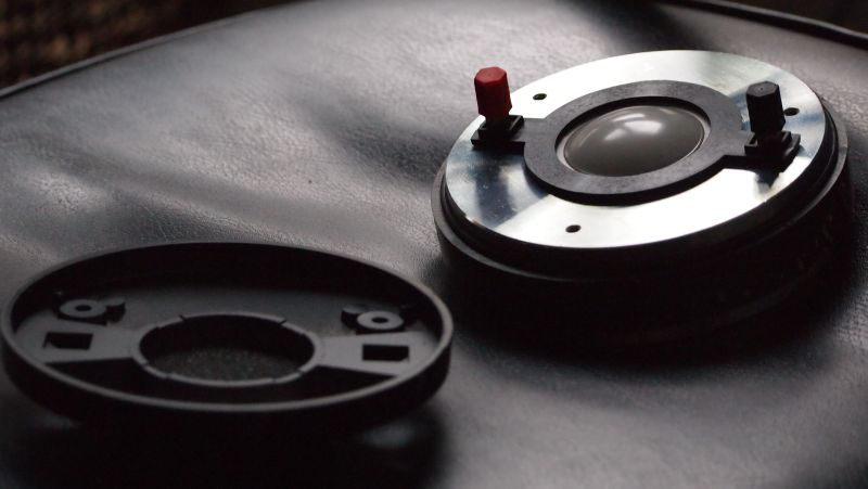
I took this picture of a compression driver cut in half about ten years back, and you can see the curvature of the diaphragm and the phase plug.
An externally hosted image should be here but it was not working when we last tested it.
It's like radians of a circle, you want all of those pie slices to be equidistant from the focal point*
Good news though!
If you sit down and think about this for a bit, you'll notice that it MIGHT be possible to use flat wavefront in a 'reverse paraline'. Basically you would distort the shape of the Paraline so that it takes a flat wavefront and produces a flat exit. This MIGHT be possible, by going the same route that a normal Paraline does to CURVE the wavefront.
Very interesting stuff!
I'm not 100% sure it's possible, but very interesting! You might be able to scale this up for subs or midranges too.
- Home
- Loudspeakers
- Multi-Way
- Square Pegs