Thanks a lot for answering many of my questions, PB. While I have learned a lot from your earlier posts about Unity and Paraline, now I am actually left with even more questions.
This may have been addressed earlier, but why do you split the Paraline into 4 segments in your spreadsheet/Hornresp? This is the eye-shaped Paraline?
- Referring to the patent its difficult to see why you split the Paraline into 4 segments, each with a quarter of the total pathlength. Wouldnt the pathlength of section D1 and D2 be close to the total pathlength? If S1-S2 was the entry and rather short, S2-S3 was D1, S3-S4 was the 180 deg. bend and also short, and S4-S5 was D2, I could understand the consept. Could someone please explain?
- If the Paraline horn is a round horn with 360 degree horisontal spread (like the filling in an Oreo cookie) thats folded, why do we need to split the path into sections? Do the folds in the Paraline truncate or in other ways affect the pathway in such a way that we need to section the horn to simulate the effect? If not, then why do we need more than S1 as the entrance and S2 as the exit/slot to simulate a Paraline horn? Is not the pathway expanding in a linear fashion between those two points?
This is fun!! Just to make my design target clear, the overall goal is to have a FLH bass/midbass 80-400Hz with proper hornloading but I could settle with somewhat less BW. My interest in the Paraline, besides a fascination for brilliant consepts, is the promise of reducing the depth of the horn, and a hope that the folds in the Paraline would not affect the upper bass/lower midrange to much. But if a Paraline mainly is a directivity-device and do not contribute much to the loading in the lower frequencies, I guess I am better of with a "scorpion-style" midbasshorn with only one, gentle bend. My limited experience with folded FLH >250Hz has not been promising.
Like many other, its not the overall bulk of a hornsystem thats the problem, its the depth of proper horns. The system will use distributed subs <80Hz and large horn >400Hz.
Hornresp has no way to model the bends in the Paraline.
I'm modeling the Paraline using the volume of the radial rings in the wavefront expansion.
So my model doesn't include two things:
1) it doesn't account for the reflectors. We have no way to account for it, so we have to pretend it's not there, unfortunately. In the real world, the reflectors appears to roll off the highs.
2) My model uses an arbitrary size for the horn throat. This is a bit tricky also, since the "true" value of the throat is somewhere between zero and the size of the radiator that's driving the Paraline. For instance, if the radiator at the apex of the Paraline is a 10cm compression driver dome, then the 'true' size of the throat is somewhere between zero and 10 cm.
If you really want to go crazy with this, the docs for Akabak describe a model for a compression driver that includes virtually everything. Hornresp is easier to use of course, and gives results that get us 'in the ballpark.'
s ... And actually, only the first part of the expansion is 360 degrees... the second fold is not, otherwise it would not converge on a straight line...?
Good point... a horn formed from 2 discs has a mouth area of 3.1416 * diameter * plate spacing. A Paraline has a mouth area of 2 * diameter * plate spacing.
It's hard to model though, because the distance from the throat to the fold varies from half the horn length to the full horn length.
Last edited:
Good point... a horn formed from 2 discs has a mouth area of 3.1416 * diameter * plate spacing. A Paraline has a mouth area of 2 * diameter * plate spacing.
It's a diverging horn from the throat to the old and then converging from the fold to the mouth. It's hard to model though, because the distance from the throat to the fold varies from half the horn length to the full horn length.
I posted the math for how wide the Paraline mouth should be. It's somewhere in this thread. IIRC, it's (pi * internal height.)
For instance, with an internal height of 0.635cm, the Paraline mouth measures 1.99cm wide.
Note the width will be wider due to the reflector that's typically placed in the mouth.
Making the mouth wider doesn't compensate for the different expansion rate in the post-fold part of the horn. You'd need to make the plate spaciing divergent in the latter half of the horn. (It would have to taper from 0.635 cm at the fold to 1.99 cm at the centre of the mouth slot, tapering back down to 0.635 cm at the ends of the slot.)
Making the mouth wider doesn't compensate for the different expansion rate in the post-fold part of the horn. You'd need to make the plate spaciing divergent in the latter half of the horn. (It would have to taper from 0.635 cm at the fold to 1.99 cm at the centre of the mouth slot, tapering back down to 0.635 cm at the ends of the slot.)
The expansion rate isn't different after the fold.
The horn expands in 360 degrees in one dimensions, and zero degrees in the other. It expands out like rays of sunshine. That's one of the reasons I named my thread on the Paraline 'Sunshine'
The expansion rate isn't different after the fold.
The horn expands in 360 degrees in one dimensions, and zero degrees in the other. It expands out like rays of sunshine. That's one of the reasons I named my thread on the Paraline 'Sunshine'
You might care to re-evaluate your conclusion.
The expansion rate from the throat to the fold is standard radial horn parabolic. The expansion rate from the fold to the mouth is somewhat less.
More specifically, the expansion rate from the throat to the ends of the mouth line is standard radial horn. Now look at 90 degrees, from the throat through the fold to the centre of the mouth line.
Simple math, just compare the mouth areas.
Standard radial horn formed of 2 parallel discs, 20 cm diameter, 2 mm apart:
Mouth area = 3.14 * 20 * 0.2 = 12.56 cm2.
Paraline with 20 cm diameter (mouth length) and 2 mm plate spacing:
Mouth area = 2 * 20 * 0.2 = 8 cm2.
(Making the mouth slot wider does not compensate for lack of expansion earlier in the horn.)
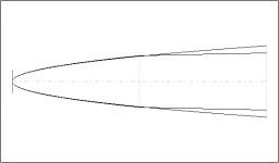
Simulating this is difficult, because the point at which the expansion rate changes varies from half way down the horn to its mouth. Probably the best that can be done with Hornresp is to use a 2-segment horn with the expansion rate of the second half chosen as an average of the two limit cases. The attached image shows the two limit cases - the expansion rate from the throat to the ends of the mouth line versus the expansion rate at right angles to the mouth line. (The mouth areas follow the two calculations above.)
Attachments
Last edited:
http://www.diyaudio.com/forums/multi-way/153831-styrofoam-smith-horn-2.html#post1964569
Wow, look at that date, 29 Oct 2009...
Too bad I never followed up.
Totally forgot I ever had the idea.
Wow, look at that date, 29 Oct 2009...
Too bad I never followed up.
Totally forgot I ever had the idea.
I'm now thinking Unity here as well...
An if that news weren't strange enough. I'm also thinking what-if
you fold a Smith horn???? Folded on a parabolic curve... Can it be
tricked to exit from a flat front slot in one phase, as-if a line array?
Does the non-expanding part (after the parabolic) serve as a plane
wave tube?
And if that still ain't strange enough. Also thinkin Smith Unity to
replace the driver in a Karlson type enclosure. That would mean
loading the backs of the cones to the K box. Not sure how thats
gonna mess with EBP??? As most advice I've heard is to seal the
backs of such cones in attempt to raise both Fs and EBP.
I don't think Styrofoam will be the material of choice, but might
still get abused here and there...
Last edited by kenpeter; 29th October 2009 at 02:56 PM.

On this forum, Tom Danley has given us some information on some interesting new ways to fold a horn. These new horns include the VTC Paraline, which combines two compression drivers on one horn, and the Jericho J4, which uses what he calls a 'layered combiner' to load 64 compression drivers on one horn.
Unity Paraline - YouTube
I decided to build one this week.
Once you figure out how they work, they're a lot of fun to build. They're waaaaaaaaaay easier to assemble than a Synergy horn, that's for sure. I built this one in under two hours.
The device that I built is neither a Paraline nor a layered a combiner. For the most part, it's a simplification of the Paraline. (I could build a *real* Paraline, but I didn't want to for this project, I wanted to do a 'proof of concept' first.)
As usual, my projects are completely kludgey and rushed and crude, but you get the general idea.
In the video, I think you'll notice a few things:
#1 - Although my compression driver appears to be firing through a block of wood, I have extension out to at least 18khz
#2 - Have you ever seen a horn that was less than four centimeters deep?
#3 - Have you ever seen a Unity horn that was smaller than a 8" woofer?
Hope you enjoy the vid.
Diagrams of the layered combiner are now available. The patent number is US20120328140 A1

An externally hosted image should be here but it was not working when we last tested it.
Crunched some numbers with my calculator, and I think I came up with a schematic that will curve the wavefront of a flat driver, like the BGs:
![bg%2520layered%2520combiner-2.jpg]](https://lh6.googleusercontent.com/-mcx95HTyyf0/URlwVYm_gpI/AAAAAAAAE_Q/yqIiKl5A_oU/s800/bg%2520layered%2520combiner-2.jpg])
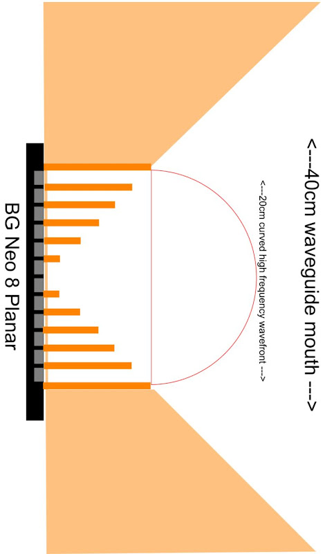
Here's the original schematic. See how the additional length on the edges creates a delay? Basically we want the center of the diaphragm to 'lead' the edge by about four centimers.
I have a bunch of sawafuji ribbon tweeters and decided to make a 4 paraline array to test how they work. I made an entry deflector that only deflects the radial holes from the tweeter, plugging the center hole. By using the paraline I will need a lot less tweeters (if I wanted to build a tall array). The one surprise is that the tweeter goes quite low. The vertical directivity is as predicted, big difference from the response in front of the array versus 8 inches on top of it. SPL levels up/down the array is constant so the paralines integrate well vertically. I attached some measurements although it is not a great setup as I want to stay air conditioned.
Building the paraline was not too difficult. I made a router template with indexing holes to repeat the cuts. I did a layer at a time. Next time I think it is easier and more precise to do the three eye layers at the same time.
In the end I cheated a little. I had made the template to use a 1/4 inch spiral bit which I did use, but I did not have enough 1/4 inch material to do it. I used 3/8 material instead. Also the front layer with the exit slot is not 3/8, it is 1/8 inch.
I want to try get some measurements with the array wedged into the corner and use the 90 degree wall as a horn.
Here's another driver that might make a promising mid range in a Paraline:
HiWave BMR12 Compact 2" Full-Range Square Speaker 12W 8 Ohm 299-208
An externally hosted image should be here but it was not working when we last tested it.
Here's why this is a cool driver:
1) it's under six bucks
2) Because the diaphragm is flat, you don't need a compression chamber. Basically the reason we use the compression chamber on the mids is so that the compression driver doesn't reflect off the midrange drivers. But the compression chamber creates a plethora of problems, particularly by limiting the top end of our mids. The BMR driver solves that. On the downside, distortion is higher without the compression chamber. I can live with that.
3) Due to the very small size of the BMR driver, you can do some cool stuff with it. If I were to use this, I would orient the BMR drivers into a ring around the compression driver. So basically you have a pulsing 'ring' of sound. This keeps all the pathlengths the same, which simplifies the crossover, improves off-axis response, improves intelligibility, makes the response more uniform, improves imaging.
Rings are your friend.
Last edited:
Talking about Hiwave got me thinking.
Why not go all the way and use the wall in the paraline as a speaker?
No surrounds on them to disturb the sound.
http://www.hi-wave.com/products/audio-exciters.php
HiWave HIAX25C10-8/HS 25mm Classic Efficient Exciter 8 Ohm 297-2105
I played around with vibration speakers before and depending on the surface you can actually get som decent midrange from them.
But, I wonder what kind of material and how thick one should use to get the most out of these exciters.
And where should we place them?
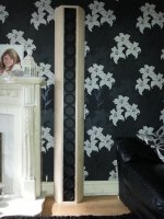
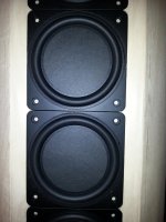
Line Array with 16 BMR per channel
These pics were taken before I screwed in the drivers ( 128 screws!) and put on the black felt covers.
Anyway they are pretty amazing...!
I agree with Patrick, off axis and on axis, everywhere in the room is even balanced sound.
A great benefit is that when you Eq on axis for driver / room artifacts, it sounds just the same off axis...
The Sd is 960 ( more than a 15 inch driver!) per channel so even when you add in low end boost and power them with big amps the driver excursion is still under 2mm ( plus / minus 1mm)
I wire them as 4 groups of 1 Ohm in series so end up with 4 Ohm load but a sensitivity of 100dB per watt @ 1 meter!
I am going to start a build thread next month when I build another few pairs and I can take more pics during assembly.
Cheers
Derek.
Attachments
The vibration element makes sound radiate from the entire (more or less) plane, which is a good thing for a wall mount but bad for a Synergy style horn, as the radiating elements can no longer be kept within 1/4 wavelength, so off axis response would be peaky.Talking about Hiwave got me thinking.
Why not go all the way and use the wall in the paraline as a speaker?
I played around with vibration speakers before and depending on the surface you can actually get som decent midrange from them.
But, I wonder what kind of material and how thick one should use to get the most out of these exciters.
And where should we place them?
But if we take a solid ring that pushes on a ringmembrane instead of the whole area we get something like a bms 4590 om steroids.
The exciters pushes on the ring that transfers the energy to a flexible membrane that is of the right shape and size and at the right distance from the compression driver.
In this link there is a drawing of the bms 4590.
www.pa-forum.de • Thema anzeigen - BMS4590 an Vitavox 4cell Horn, Messergebnisse!(aktualisiert)
An annular ring diaphragm has far less surface area than a cone diaphragm of the same diameter, and the small diaphragm area of the BMS 4590 is further limited by it's Xmax of less than 1mm.But if we take a solid ring that pushes on a ringmembrane instead of the whole area we get something like a bms 4590 om steroids.
The exciters pushes on the ring that transfers the energy to a flexible membrane that is of the right shape and size and at the right distance from the compression driver.
Inexpensive cones mounted in an offset horn can far exceed the output potential of a BMS 4590 in the low midrange.
Ok, so I ran another test to see the individual FR of the original paraline used in the array. Both single paralines show the bumps. The 3/16 paraline shows extended HF. 3/16 router bit vs 1/4 router bit.
Also, the interaction between the paralines in the array is lowering the HF and bringing up the mids. I don't have any experience with arrays so I can't explain what may be happening. What happens to the phase as you go from the the center of the slot to the ends?
People who have built Paralines have noticed that it's really hard to get a lot of high frequency output from the device. And this behavior is hard to predict, because hornresp isn't really designed to model loudspeakers past five or ten khz. (At these ultra short wavelengths the horn 'begins' way back inside of the compression driver, making it hard to model.)
While doing some research for my next set of speakers, I stumbled across a couple more factors which might be impacting high frequency response in a Paraline.
1) In a conical horn, the 'local flare rate' of the horn is changing as you move down the horn. At the throat the flare rate is very high, and it gets lower and lower as you get closer to the mouth. A Paraline is a radial horn, and a radial horn has a flare rate that's *similar* to a narrow angle conical horn, but it's NOT the same.
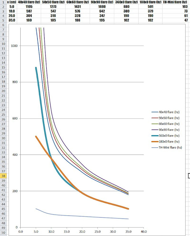
I think this could be a factor in the high frequency response of the Paraline. Basically at the throat a conical horn has a higher flare rate, which is better suited to high frequency loading. A few inches down the throat, the flare rate of the Paraline and a conical horn are getting closer - but the conical horn still has a higher flare rate. (IE, the conical horn is 'better suited' for high frequency loading than the radial/Paraline horn.)
The graph above shows this; the turquoise line is radial expansion, like in a Paraline. The dark red line is the flare rate of a 50x50 conical horn, like the flagship of the DSL line, the SH-50. See how the turquoise line is lower at all times? Basically, the Paraline is loading the lower frequencies with greater efficiency.
Now, I want to stress that I'm not using Paralines for their efficiency, I'm using them because they're compact and they give me a radiation pattern that works for my projects. But if anyone is wondering why the high frequencies on a Paraline are a bit muted, the reason may not be that the highs are muted; the real reason may be that the lower frequencies are just getting amplified more efficiently than the highs.
As they say in software, "that's not a defect that's a feature." Because one nice thing about good low frequency loading is that it reduces harmonic distortion by reducing excursion, which means we can add a lot of EQ in the top octaves without making the driver sound 'harsh.'

Here's a sim to illustrate what I mean. The sim shows the response of a B&C compression driver on a 360 degree radial horn, versus a 60x60 conical horn. In the sim we see that the lower we get in frequency, the radial horn produces more output on axis. On the downside, the radial horn is absolutely huge. (I used the same mouth size for both horns; since the radial horn has a much narrower angle, it's size dwarfs the conical horn.)
The main reason I did the sims was to illustrate the increased output of the radial horn - which may explain why the high frequency output of a Paraline seems 'muted.'
In the last post, I showed some data that indicates that the high frequency loading of a radial horn like the Paraline isn't well suited to very high frequencies.
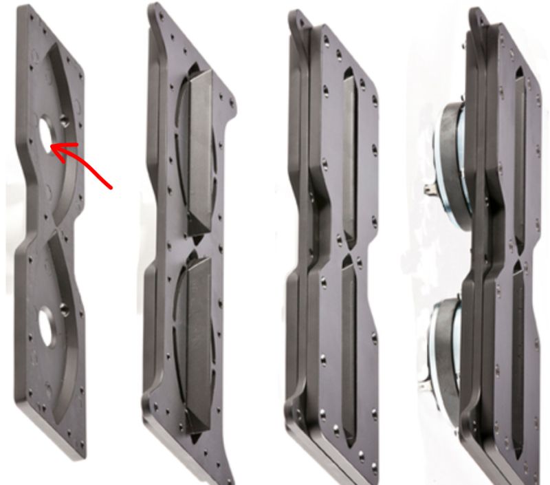
One idea I had was to 'fill in' the throat of the compression driver.
By reducing the area, right down into the compression driver, one might improve the high frequency output. (5khz and up.)
I think some of the VTC Paralines do this; there appears to be a cone shaped 'insert' in their Paraline.
One idea I had was to 'fill in' the throat of the compression driver.
By reducing the area, right down into the compression driver, one might improve the high frequency output. (5khz and up.)
I think some of the VTC Paralines do this; there appears to be a cone shaped 'insert' in their Paraline.
- Home
- Loudspeakers
- Multi-Way
- Square Pegs