I've been doing some thinking about paralines and what the wave front will "look" like. I pretty clearly understand how the width equaling half the height would produce equal paths and therefore a vertically in-phase wave front. I'm trying to get an idea of the attenuation effect along the height of the wave front. In my mind it looks like it would be a function of the angle of incidence off of the parabolic reflector. If the paraline is made taller (skinnier is probably better) it would introduce both more delay and more attenuation further from its center, correct?
Does anyone know of a method to calculate or approximate the attenuation effect? I've been discussing this with a few guys on another forum. I think there could be some interesting uses based on the combination of delay and shading of this line source...pseudo-CBT anyone?
Does anyone know of a method to calculate or approximate the attenuation effect? I've been discussing this with a few guys on another forum. I think there could be some interesting uses based on the combination of delay and shading of this line source...pseudo-CBT anyone?
Last edited:
I've been doing some thinking about paralines and what the wave front will "look" like. I pretty clearly understand how the width equaling half the height would produce equal paths and therefore a vertically in-phase wave front. I'm trying to get an idea of the attenuation effect along the height of the wave front. In my mind it looks like it would be a function of the angle of incidence off of the parabolic reflector. If the paraline is made taller (skinnier is probably better) it would introduce both more delay and more attenuation further from its center, correct?
Does anyone know of a method to calculate or approximate the attenuation effect? I've been discussing this with a few guys on another forum. I think there could be some interesting uses based on the combination of delay and shading of this line source...pseudo-CBT anyone?
My renewed interest in the Danley Paraline was due to an email I received from someone on this forum, asking me about the CBT. I'd first noticed the Paraline in the Genesis horns about a year and a half ago. My first stab at understand the Paraline was in a thread named 'I don't Understand' here on this forum. (And I didn't, believe me!) I also started a thread named 'Sunshine' here on this forum. There's some good tidbits in both, and they're worth a read.
Back to your question -
Why is the Paraline shaded, and how?
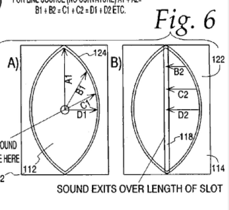
In this picture from the Danley patent, it appears that the loudspeaker energy is evenly spread across the mouth of the Paraline. This is not the case. The picture is misleading IMHO, because D2, C2 and B2 are evenly spread out across the mouth. In the real world, the loudspeaker energy is highly concentrated in the center of the Paraline.
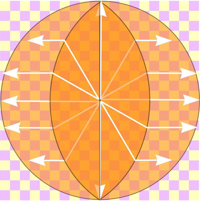
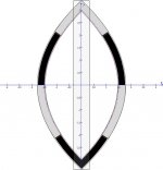
Here is my own illustration of the Paraline radiation. Compare it to the patent. In my picture, I've staggered each line so that they're arrayed outwards from the origin with the same gap between each line. (IE, the energy from the loudspeaker is radiating in 360 degrees, with an even coverage in all 360 degrees.)
See how there's barely any energy that's getting to the top and the bottom of the Paraline mouth?
That's why the Paraline is shaded, like a CBT. There is simply more energy exiting the center of the Paraline mouth than the edges.
For a line array, this is A Good Thing. It makes it easier to array a series of Paralines.
On the downside, I do believe that this 'shading' is one of the reasons that the polar response of the Paraline is not as good as a conventional conical horn. Basically in the first half of the Paraline, the half that exists prior to the reflector, you have a constant expansion rate. But once you hit that reflector, the expansion rate will change depending on angle. That's a bit wonky, and I believe it may be contributing to the strange polar response plots that have been posted, particular in the vertical axis of the Paraline.
Patrick,
Excellent analysis here from common sense observations. If we could put a pressure microphone into the paraline we could measure the pressure gradient across and vertically in the slot and that would show more what is actually going on there. As you say from this point forward to the acoustical matching with a conic section waveguide we could also see major pressure gradients with the surfaces at specific points. After a distance the pressures would even out but how that is affecting the polar response of the wavefront is something I haven't seen an analysis of at this point. I would love to see an accurate polar response curve with instrumentation microphones and not uncalibrated devices in both the vertical and horizontal planes with a turntable moving the waveguide about its center. I know it is hard to get accurate response curves in anything but a very large anechoic chamber, but a test with the device outside in open space would be fairly accurate if pointed up and not along the ground plane. A trick I have seen done but not with a horn is to have the device parallel to the ground in a hole using the earth as an infinite baffle. I digress though. I appreciate your comments here Patrick.
Steven
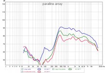
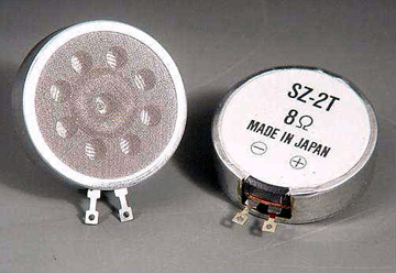
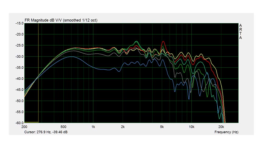
I have a bunch of sawafuji ribbon tweeters and decided to make a 4 paraline array to test how they work. I made an entry deflector that only deflects the radial holes from the tweeter, plugging the center hole. By using the paraline I will need a lot less tweeters (if I wanted to build a tall array). The one surprise is that the tweeter goes quite low. The vertical directivity is as predicted, big difference from the response in front of the array versus 8 inches on top of it. SPL levels up/down the array is constant so the paralines integrate well vertically. I attached some measurements although it is not a great setup as I want to stay air conditioned") .
.
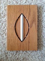
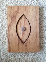
Building the paraline was not too difficult. I made a router template with indexing holes to repeat the cuts. I did a layer at a time. Next time I think it is easier and more precise to do the three eye layers at the same time.
In the end I cheated a little. I had made the template to use a 1/4 inch spiral bit which I did use, but I did not have enough 1/4 inch material to do it. I used 3/8 material instead. Also the front layer with the exit slot is not 3/8, it is 1/8 inch.
I want to try get some measurements with the array wedged into the corner and use the 90 degree wall as a horn.
.Building the paraline was not too difficult. I made a router template with indexing holes to repeat the cuts. I did a layer at a time. Next time I think it is easier and more precise to do the three eye layers at the same time.
In the end I cheated a little. I had made the template to use a 1/4 inch spiral bit which I did use, but I did not have enough 1/4 inch material to do it. I used 3/8 material instead. Also the front layer with the exit slot is not 3/8, it is 1/8 inch.
I want to try get some measurements with the array wedged into the corner and use the 90 degree wall as a horn.
Attachments
-
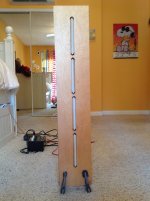 IMAGE_3541451E-147D-422C-B025-E5759071D7FF.JPG78.3 KB · Views: 1,566
 -
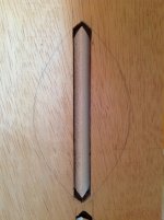 IMAGE_90AF4ADE-DCFE-424B-824D-47AE34A8CEB5.JPG71.3 KB · Views: 778
 -
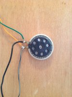 IMAGE_8A4B640E-90F7-4170-9812-DEF033005E66.JPG102.8 KB · Views: 773
 -
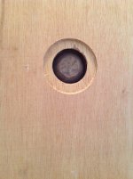 IMAGE_48C946B2-14C3-43C8-8D69-0ABB79B520FF.JPG74.3 KB · Views: 377
 -
 paraline array.jpg141.6 KB · Views: 487
I have a bunch of sawafuji ribbon tweeters and decided to make a 4 paraline array to test how they work. I made an entry deflector that only deflects the radial holes from the tweeter, plugging the center hole. By using the paraline I will need a lot less tweeters (if I wanted to build a tall array). The one surprise is that the tweeter goes quite low. The vertical directivity is as predicted, big difference from the response in front of the array versus 8 inches on top of it. SPL levels up/down the array is constant so the paralines integrate well vertically. I attached some measurements although it is not a great setup as I want to stay air conditioned
Building the paraline was not too difficult. I made a router template with indexing holes to repeat the cuts. I did a layer at a time. Next time I think it is easier and more precise to do the three eye layers at the same time.
In the end I cheated a little. I had made the template to use a 1/4 inch spiral bit which I did use, but I did not have enough 1/4 inch material to do it. I used 3/8 material instead. Also the front layer with the exit slot is not 3/8, it is 1/8 inch.
I want to try get some measurements with the array wedged into the corner and use the 90 degree wall as a horn.
WOW
Nice work, and I appreciate the measurements.
Speaker Stuff
Is this basically the same ribbon as what ApexJR is selling?
If so, it might make a heck of a candidate for an inexpensive alternative to the Keele arrays. Here's what I'm picturing:
An externally hosted image should be here but it was not working when we last tested it.
- I'm picturing an array with ten of the planar ribbons per side ($50)
- low frequencies are handled by and good and inexpensive midbass. The folds at Bottlehead.com sold an array that used eight of the woofers. Part # is 55-1870. (MCM Audio Select 5'' Aluminum Cone Woofer | 55-1870 (551870) | MCM Audio Select) Cost is $92 per side.
- The array is curved, like the Keele CBT.
Total parts cost is $142 for the drivers. That's less than the cost of one good midrange from Scan Speak. But for $142 we get the following:
- More midbace surface area than a 15" woofer
- An attractive slim enclosure
- curving the array, and using Paraline reduces the nasty problems of conventional arrays, particularly comb filtering
- Paralines have a hard time getting to 20khz, but with ten tweeters we can use a passive network to extend the response. Basically sacrifice efficiency at 1khz for output at 20khz.
- I've heard the 'straight 8s', and felt that the tweeter was hopelessly 'detached' from the midranges. Basically there's a really wonky transition from midrange to tweeter, and it makes the high frequencies sound 'detached' and unnatural. I believe this is mostly due to the fact that the midbasses have much higher output, efficiency, and the midbasses have a radiation pattern that's completely different than the tweeter. Long story short, the 'Straight 8s' sound good if you ignore the high frequencies.
Might be quite a giant-killer.
This is just too good, I have a million projects to deal with right now, but the results you're getting are spectactular for a $20 investment.
I just placed an order for 12 of the ribbons from ApexJR.
Get 'em while you can; it sounds like he doesn't have many left.
Note that the Paraline really works best with a very very small driver. This is due to the pathlength differences. For instance, if we want to play to 20khz, the radiator should be no larger than 0.17"(!). This is based on the following formula:
(speed of sound / maximum frequency / 4) =
(13500 inches per second / 20000 / 4) =
= 0.16875" (!!!)
The reason that compression drivers work nicely is that they focus all of their energy into a converging wavefront. Basically the sound at the exit of the compression driver is focused into a smaller area than what's coming off of the dome INSIDE of the compression driver. Conventional drivers do not have a phase plug, so due to that, conventional drivers need to be really small to play high frequencies on a Paraline.
Long story short - if you want to use a conventional driver in a Paraline, it should be small. Small and flat is even better. Small, flat and cheap is the best of all, and it looks like we've found a winner when it comes to that!
As I mentioned, get 'em while you can, Apex JR can be reached at 818-248-0416
I just placed an order for 12 of the ribbons from ApexJR.
Get 'em while you can; it sounds like he doesn't have many left.
Note that the Paraline really works best with a very very small driver. This is due to the pathlength differences. For instance, if we want to play to 20khz, the radiator should be no larger than 0.17"(!). This is based on the following formula:
(speed of sound / maximum frequency / 4) =
(13500 inches per second / 20000 / 4) =
= 0.16875" (!!!)
An externally hosted image should be here but it was not working when we last tested it.
The reason that compression drivers work nicely is that they focus all of their energy into a converging wavefront. Basically the sound at the exit of the compression driver is focused into a smaller area than what's coming off of the dome INSIDE of the compression driver. Conventional drivers do not have a phase plug, so due to that, conventional drivers need to be really small to play high frequencies on a Paraline.
Long story short - if you want to use a conventional driver in a Paraline, it should be small. Small and flat is even better. Small, flat and cheap is the best of all, and it looks like we've found a winner when it comes to that!
As I mentioned, get 'em while you can, Apex JR can be reached at 818-248-0416
Mine are dipole, holes on both sides. Not sure what differences performancewise.
So i am confused about needing to curve the paraline array. Isnt the output vertically planar?
Speaker addict has some inexpensive drives that may work.
Alfredo
Check out the DB Keele CBT array for a pile o' math on the reasons why curved arrays are superior to flat arrays.
IMHO, the math is nice, but the explanation is just common sense. In an array, all of the drivers are interacting with each other. For two drivers to sum well, they need to be within about 1/4 wavelength of each other. But that is a STRICT requirement. For instance, that means that two tweeters playing 2khz need to be within 1.75" of each other to sum well. That's not always easy to do.
So curving the array is just an incredibly easy way to improve an array. The curvature doesn't change the center-to-center spacing by an appreciable degreee, but it *does* reduce comb filtering, because sound gets increasingly more directional as frequencies rise.
As a bonus, it also distributes room modes.
All in all, I can't think of any good reason NOT to curve an array, except that it's a p.i.t.a.
Need to read up on the CBT.
Forgot to mention that the two back layers of the paraline are also 1/8". The inner has a 1" hole which is exactly the diameter of the outer ring of holes of the tweeter. The outer layer has a hole of 1.5 inches, exactly the diameter of the tweeter so it is quite a nice fit.
I have attached the drawing I used to make the router template.
will keep an eye on your project.
Alfredo
Attachments
I'm just sayin' try the outer edge of the parabola only.
Avoid the "round" part near the middle.
Why? Cause middle part is all nearly the same reflection
distance back toward the driver. Maybe aggrivates dips?
Anyways, also thinkin you might fold this down the
centerline, and then drivers would be on opposite sides,
instead of crowding each other.
Aplologies to drawing above, I totally butchered it...
Attachments

Is directivity control at 100Hz a problem worth this much effort to fix it?
I wouldn't suspect it is, what I'm interested in is seeing a large (6 or 7 foot?) radiating area, and how it would sound. (plus it would look brutal as f***).
I'm just sayin' try the outer edge of the parabola only.
Avoid the "round" part near the middle.
Why? Cause middle part is all nearly the same reflection
distance back toward the driver. Maybe aggrivates dips?
Anyways, also thinkin you might fold this down the
centerline, and then drivers would be on opposite sides,
instead of crowding each other.
Aplologies to drawing above, I totally butchered it...
The above measurement is from natehansen66, and gives us some 'food for thought' on the question of reflections causing dips.
The thing about the dips which has me perplexed is that they must be VERY short dimensions. For instance, in nate's measurements we see a dip at 11khz. That frequency is 3cm long. Typically we would expect a dip to be caused by sound reflecting back and being out of phase. IE, it travels one quarter wavelength, runs into something, comes back again, and is now 180 degrees out of phase, which causes a dip.
But if my understanding of dips is correct, that means that the dip at 11khz in Nate's measurement is being caused by a reflection at a dimension that's just 0.75cm in distance.
To me, that seems suspiciously consistent with the *height* of the inner duct. In other words, varying the *shape* of the Paraline won't get us a lot of benefit, but varying the *height* will.
An externally hosted image should be here but it was not working when we last tested it.
The easiest way to vary the height of the Paraline, IMHO, is to dimple it.
The above measurement is from natehansen66, and gives us some 'food for thought' on the question of reflections causing dips.
I couldn't remember what exactly those measurements were of, so I had to look at my post that went with it. That Paraline was using a piece of cardboard for the driver mount plate, with 2 FR88's flanking an old 1" soft dome tweeter. There was little to no precision in the mid entrance holes, and they were about .75" in diameter.
I'm making new driver plates right now (had one built but goofed on a measurement and threw the whole thing off center), and I've got a horn shell done. I'll see if I can get some new measurements of a more refined Paraline on a 60x40 conical horn with a 20" wide x 25" tall mouth and see what happens.
What are you thinking with the dimple idea PB?
Basically there seems to be a dip in the response which correlates with a dimension of about 0.3" or 0.75cm.
That dip may be consistent with the height of the Paraline.
Therefore, dimpling the Paraline might smooth out the response. It basically varies the height of the duct.
The thing that's vexing me is that the dip in response gets lower as the angle varies. And I wouldn't expect that to occur if the dip is caused by the interior height of the Paraline. (IE, if the dip gets lower as frequency gets lower, one would expect that it's due to a reflection that varies based on angle.)
I made a single paraline but this time it is all 3/16 to see if the HF improved. Indeed it did, but peaks around 1.5k and 4.5k are prominent. I wonder if these are related to the length of the paraline whose fold is 3 inches long per side. Wavelength of 1.5K is 9 inches, 4.5K is 3 inches. Is this a resonant mode? Maybe it is just a coincidence.
Attachments
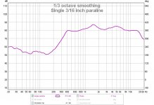
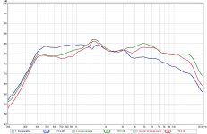
Ok, so I ran another test to see the individual FR of the original paraline used in the array. Both single paralines show the bumps. The 3/16 paraline shows extended HF. 3/16 router bit vs 1/4 router bit.
Also, the interaction between the paralines in the array is lowering the HF and bringing up the mids. I don't have any experience with arrays so I can't explain what may be happening. What happens to the phase as you go from the the center of the slot to the ends?
Also, the interaction between the paralines in the array is lowering the HF and bringing up the mids. I don't have any experience with arrays so I can't explain what may be happening. What happens to the phase as you go from the the center of the slot to the ends?
Attachments
Some people like dipoles. Good drivers for dipole use are hard to find - the drivers have to have an equal radiation pattern front and rear. Magnets and other structures get in the way of the rear radiation. So how about a dipole Paraline? The "classic" Paraline folds so that both "sides" of the folded line exit beside each other at the front. How about folding so that one "side" exits at the front and the other exits at the rear? The driver does get in the way for the rear exit, but the mounting and "folds" can be offset so that the exits are still straight. (Same geometry as a classic Paraline with two drivers mounted face-to-face.)
Edit: Oops, the trouble with thinking out loud is that it's easy to forget to remove one's foot first...
the above wouldn't be a true dipole, as the front and rear radiation would be in phase. Shouldn't be an issue for HF use, though.
Edit: Oops, the trouble with thinking out loud is that it's easy to forget to remove one's foot first...
the above wouldn't be a true dipole, as the front and rear radiation would be in phase. Shouldn't be an issue for HF use, though.
Last edited:
Basically there seems to be a dip in the response which correlates with a dimension of about 0.3" or 0.75cm.
That dip may be consistent with the height of the Paraline.
Therefore, dimpling the Paraline might smooth out the response. It basically varies the height of the duct.
The thing that's vexing me is that the dip in response gets lower as the angle varies. And I wouldn't expect that to occur if the dip is caused by the interior height of the Paraline. (IE, if the dip gets lower as frequency gets lower, one would expect that it's due to a reflection that varies based on angle.)
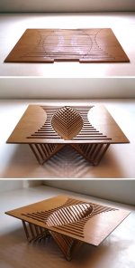
Here is an interesting visual it was just so similar looking I thought I would post it. Please forgive the interuption. Best regards Moray James.
Attachments
- Home
- Loudspeakers
- Multi-Way
- Square Pegs