Mitch,
Ask me about a normal exponential or hyperbolic and I can answer with authority, but here I am treading in another realm. Not really that different but slightly is the real answer. These paraline and horn combinations are following more of a constant directivity model, only the initial section is unusual. The concept is a way to combine different devices on a single waveguide with all devices have equivalent dispersion down to the mouth cutoff frequency.
Ask me about a normal exponential or hyperbolic and I can answer with authority, but here I am treading in another realm. Not really that different but slightly is the real answer. These paraline and horn combinations are following more of a constant directivity model, only the initial section is unusual. The concept is a way to combine different devices on a single waveguide with all devices have equivalent dispersion down to the mouth cutoff frequency.
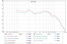
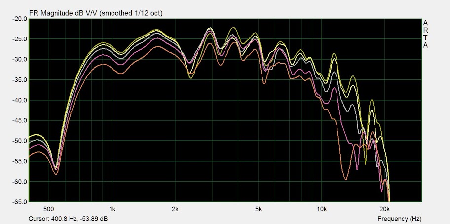
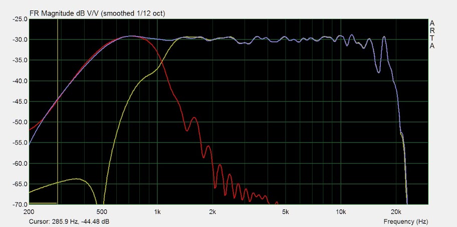
Last weekend, I build a Paraline with 20 centimeter height and 4.34 cm wide (30 degree vertical) with 3mm thick acrylic and put B&C DE500 as tweeter.
Since, I don't understand how to calculate the wide of the opening slot, so I made some experiment. Here is the result. Opening slot is 20 centimeter long with 6mm wide and 10 mm wide. Seem to result in the same shape except 10 mm lost some dB.
Measure with REW, indoor, gate 8ms
Since, I don't understand how to calculate the wide of the opening slot, so I made some experiment. Here is the result. Opening slot is 20 centimeter long with 6mm wide and 10 mm wide. Seem to result in the same shape except 10 mm lost some dB.
Measure with REW, indoor, gate 8ms
Attachments
Last edited:
Sunra,
Yes, the height of each chamber is 3mm. But I cut it by hand so very crude.
I didnot use any deflectors because I don't know how to calculate the size and shape. My compression driver, B&C DE500, has grill at the opening so I can not use deflector at the entry point.
Can anyone guide me on the size and shape of the delector at the exit slot, please.
You'll need to do some trigonometry.
This post shows how it looks for a "standard" Paraline:
http://www.diyaudio.com/forums/multi-way/217298-square-pegs-6.html#post3153897
You'll need to move the focus closer to the vertex (same as making the curve shallower) to get your desired vertical dispersion.
Don,
Thanks for referring to my post. By moving the focus closer to the vertex, you no longer have reflections that are all vertical in the graph (or horizontal on a real paraline), if I am thinking correctly. In order to increase vertical directivity, we need a shape that will have all reflections in the same direction like the graph, but with a 'spherical' delay.
A hyperbola has the reflecive property that if a source is at one focus, the reflection will be as if the rays are coming off the other focus. But this means that in a paraline, the reflections will not all be perpendicular to the output slot. Not sure if it really matters for small dispersion angles, but for large ones, you can have some strange things happen.
Here's a diagram for the hyperbolic case:
When sound comes from F1 and strikes the left part of the hyperbola, its reflection behaves as if it were coming from point source F2.
What we need is a shape that will have the property of the parabolic reflection with necessary delay to approximate a point source with some degree of programmable dispersion. I have this coming week off, but I have many projects to complete, so I will see if I can crank up the old calculus engine in my brain to help get a solution to the shape of the curve for a proper diverging paraline.
JSS
By moving the focus closer to the vertex, you no longer have reflections that are all vertical in the graph (or horizontal on a real paraline), if I am thinking correctly. In order to increase vertical directivity, we need a shape that will have all reflections in the same direction like the graph, but with a 'spherical' delay.
Thank you. I see what you're getting at. It's not quite the same situation as with light, though. The wavelengths relative to the reflector size are too different. The angles of incidence and reflection are less important than the distance from the source to the mouth. ... But as you pointed out earlier, in the case of a focussed parabolic reflector, all path lengths are equal. My head hurts... I think I've forgotten more trig than I ever learned.
I suspect that, although Nate asked to increase vertical directivity, he really wanted to decrease vertical directivity. That is, increase vertical dispersion.
That leads to another thought... To increase vertical dispersion, the wavefront that develops at the mouth of the line has to be curved. The wave has to leave the centre of the mouth earlier than it leaves the ends. This may make the straight line mouth shape less than optimum to generate a curved wave. Maybe the mouth should project outwards in a curve, looking like a section of the original radial horn, giving a shape like "pursed lips".
I suspect that, although Nate asked to increase vertical directivity, he really wanted to decrease vertical directivity. That is, increase vertical dispersion.
Doh! That's what I meant to say

Don, now we are starting to talk about other shapes that I would think would conflict with the premise of the Paraline in that it is a flat construction using diffraction effects from the the slit to the matching waveguide. I was thinking what you are now talking about here and what if the shape of the internal intermediate shape was not flat but more like a football shape and giving a radial wavefront at the slot. The surrounding shape would have to also follow the let's just call it for now an elliptical form with a thin outer shell that would keep with the thin cross sectional rules of the Paraline. Things are getting much more difficult for the amateur to produce this type of device, but if we are only talking hypothetical's here I can see many improvements on the original concept. If you were going to this complexity then I also don't see any reason that the cross sectional dimensions could not follow an exponential expansion rate in this section before joining the conic waveguide which is being used to blend multiple devices.
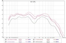
Received my BMS 4524 compression drivers today. I mounted it to a .5" piece of mdf with a 1" hole bored in it, and clamped this to my Paraline. The hole is centered with the Paraline. Still no reflector at the driver throat, and there aren't any midrange holes yet on this mounting plate. Gonna be some diffraction from my clamps probably, but here's 0-15-30-45-60 at about 1 meter. I was excited to hear a "real" compression driver finally! I'm pretty happy with the result. Eq to get it flat out through the top octave is a piece of cake, with the response falling sharply at 17.5khz as expected. That's about as high as I can hear anyways.
Horizontal:
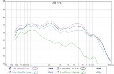
Vertical, I'm thinking this is a lot of pathlength cancellation. How do you measure a line source?
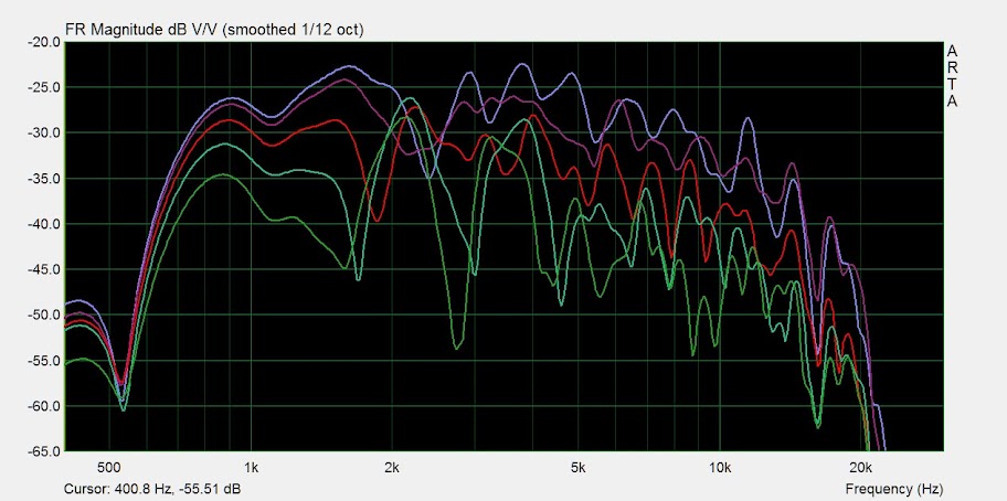
Hopefully I'll get going on the conical horn prototype tomorrow.
Horizontal:
Vertical, I'm thinking this is a lot of pathlength cancellation. How do you measure a line source?
Hopefully I'll get going on the conical horn prototype tomorrow.
Your response curves look good.Vertical, I'm thinking this is a lot of pathlength cancellation. How do you measure a line source?
Hopefully I'll get going on the conical horn prototype tomorrow.
Ideally you measure in the far field, far enough out so that the up/down angle will still result in less than 1/4 wavelength path length difference between the on axis and off axis response.
If you use a different time window (using Smaart the "auto sm") for each test as the horn is rotated, the path length difference will be compensated for.
Unfortunately, ground bounce is a measurement problem in the far field, so the horn is best pointed up in open air.
Initially I thought the Paraline upper and lower horn walls may need to be angled to prevent standing waves and reflections, found it interesting that the top and bottom horn pieces had virtually no effect on the measurement of a non-diverging Paraline.
For a home use Paraline, you could dispense with the upper and lower horn walls completely.
Art
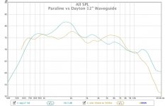
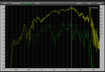
The Paraline is not particularly smooth, but has outstanding horizontal dispersion linearity on and off axis, and very narrow vertical pattern control, allowing multiple drivers to sum seamlessly.Sure would be nice to see a baseline response curve on the compression driver to see what the paraline is doing to the frequency response. This just looks pretty ragged for a compression driver.
The upper trace is a EV DH1A on a conical Maltese horn, the lower is a DH1AMT on a Paraline.
The driver's raw response may deviate slightly from each other, but the Paraline obviously does not appear nearly as "smooth".
Having replaced the Maltese horns with Paralines in my PA, the Paraline's response in multiples, after EQ, is far superior.
That said, I see no benefit (and many down sides) of the Paraline over a simple conical horn (as used in DSL's Synergy horns) for home use.
Art Welter
Attachments
Art,
The lower response curve on the paraline would be more than a problem to eq at all flat without some major peaks and dips. Even if you were using 1/3 octave smoothing that wouldn't look very pretty. Besides the shortening of the horn I don't see much anything to make me want to do this much damage to the response curve.
The lower response curve on the paraline would be more than a problem to eq at all flat without some major peaks and dips. Even if you were using 1/3 octave smoothing that wouldn't look very pretty. Besides the shortening of the horn I don't see much anything to make me want to do this much damage to the response curve.
More fun. Added 2 FR88EX stand-in mids to the Paraline. Ported the mids in about 2.25" from the center of the cd throat. 1/2" ports with 1.375" frustrum 3/8" deep into the mdf. The frustrum was done with a 1.375 forstner. When I get the mids I plan to use I'll use a narrower slot port and a larger frustrum, probably done with a router to make the walls angled.
There's a fair bit of eq on the cd to get it flat. No eq on the mid other than the out of band resonances and I boosted the low end for more midrange to make it a bit more listenable without any lower drivers. Roll off of the drivers crossover perfectly were they are on the graph, but I do have 12db filters above and below to filter out the low end from the cd and keep the aluminum cone resonances on the FR's in check.
I'm not sure I'd want to run these little comp drivers that low. Things sound a bit strained even at sane apartment levels. The solo half way into Black Sabbath - Paranoid was painful to listen to.
Adding the mids produced about a 5db dip 2k-4k and attenuated the top octave a couple db. A few of the existing peaks and dips in the top couple octaves were excited a couple db as well. Forgot to save that graph.
I'll try to get a measurement of the BMS by itself this weekend. How would I go about that? A "normal" hifi driver you'd put on a large baffle. I don't have any horns to put it on, would it be ok to measure just firing through the driver mounting plate itself?
Nate,
That looks a world better than the previous response curves, that looks usable at least. Now as far as measuring a CD without any horn or some kind of loading I don't think that it would be a very representative curve for the driver. CD response curves are typically done on a plane wave tube if it is not a response curve on a horn. You would be running the CD with no loading on the diaphragm and that wouldn't mean much. If you put much power to the driver you could have the diaphragm hit the phasing plug and I don't think you want to do that if you like your driver. Wait until it is on a device, an accurate plain wave tube is not as simple as it sounds to do.
That looks a world better than the previous response curves, that looks usable at least. Now as far as measuring a CD without any horn or some kind of loading I don't think that it would be a very representative curve for the driver. CD response curves are typically done on a plane wave tube if it is not a response curve on a horn. You would be running the CD with no loading on the diaphragm and that wouldn't mean much. If you put much power to the driver you could have the diaphragm hit the phasing plug and I don't think you want to do that if you like your driver. Wait until it is on a device, an accurate plain wave tube is not as simple as it sounds to do.
Thanks, I didn't think it would he that simple. Here's a link: http://bmsspeakers.com/index.php?id=4524_curves to the manufacturer's response.
Even if all shortest paths to exit slot are same length,
the ends of the slot are stretched taller per degree of
starting angle. The center does not expand so much.
If we put some dividers to assure each angle gets to
a uniform piece of exit. There is still the matter that
parabola inside is by necessity not evenly illuminated.
Expansion is radial and flat till we hit the parabola, but
then we may want a thinner gap at ends of our parabola
that tapers toward a gap of even width at the exit. This
to work with the dividers to keep the expansion rates
and exit area uniform.
----------
Don't know why some of Patrick's drawings overcomplicate
the merging of two drivers, one on each side. You do not
need folds that go both ways to form an eye, single parabola
would do just fine for both side mounted drivers. It does not
need to expand in a full circle.
Even if we do the eye thing with driver on the back, it seems
permissible to omit a wedge at top and bottom for support of
the stack. 360 unobstructed expansion is not a requirement.
It only needs expand vertically wide enough that an array of
drivers would not collide.
Illumination is weakest at the top and bottom anyway...
No reason to aggrivate the stretching with such oblique
angle of reflection. We truncate the eye or parabola short,
well before problem is significant enough to require dividers
and/or non-flat expansions to equalize the remaining paths
to the exit.
There may be something said for the parabola having non-
uniform length of reflection back toward the driver. If we
truncate the parabola too much, might not be as smooth
in that regard. Details, details...
Last edited:
And if we just use the outer portion of the parabola, like an offset fed horn?
Then we get the maximum smearing of the reflection time back at the driver.
Perhaps reflections from the more nearly equidistant curve, near the center
of the parabola, aggravate dips and peaks as presented in the measurements?
Suppose we have just one offset parabola above each side mounted driver,
and stack them with (or without) drivers alternating sides...
We could go above AND below, omitting a gap in the center, and fill the gap
by staggering left and right sided drivers and radial expansion cavities.
- Home
- Loudspeakers
- Multi-Way
- Square Pegs