I try the best I can to help people, but I can't always explain everything I know. Many times it can't even be put into words. I was in your shoes nearly some 20 years ago when I read one of Bruce Edgar's first horn articles. Knowledge takes time.
I understand this - the Paraline is a perfect example for me. I hadn't heard about it until Patrick mentioned it. I found myself unable to understand its geometry and how it worked - the much-quoted VTC Paraline exploded view was incomprehensible to me, as was Patrick's initial attempts to explain its geometry. I'm usually a "quick study" so I found this frustrating, and once the penny finally dropped I went into it quite deeply.
Sorry to seem dense, but I'm still confused and really want to follow this. I marked the first 2 parts of the drawing with how I think a positive going pressure would expand outward from a CD at center. Maybe I don't get both the third and fourth. Where is the pressure expanding in those?

And does the third part represent another fold again (the folds of the second drawing meeting, then folding back?) or are they just from the first fold overlapping somehow to get that?
Where does the pressure wave exit in the fourth?
Sorry again, everytime I see another sketch other than the line source-making paraline, I find I don't really understand.
Edit:
Here's a better picture with the left side starting and right side starting internal pressure waves in different colors (red and green). What are they in the 3rd and 4th parts?
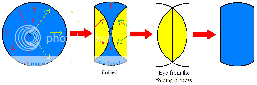
The third and fourth parts are there to show conceptually why the eye piece of the paraline is an eye shape, and why the exit/mouth is a long slot.
...
Here's a better picture with the left side starting and right side starting internal pressure waves in different colors (red and green). What are they in the 3rd and 4th parts?
That's something I struggled with too. Take a look at the second part of your illustration, with the folds. Now imagine pulling the curved edges into a straight line. You have to pull the top and bottom in further than the middle. Instead of curved edges and straight folds, you now have straight edges and curved folds. You can model this with a circular piece of cloth.
Or, imagine a bicycle wheel with no rim. You have a hub with spokes radiating out from it. This is like the first part of your drawing - sound radiating out from the centre. Now fold over each spoke so that it folds back on itself ("bent double") and its end rests on a vertical line running through the hub. The top and bottom spokes will not be bent at all, and the "horizontal" spokes will be bent at their midpoint. You will now have the outline of a Paraline.
Don Hill,
I agree with you 100% on this. Everything we design is a decision on what factors we can fudge, which are the most important and what compromises we can reasonably get away with. I have nothing against the Paraline, I actually think it is a rather cleaver way to foreshorten a waveguide. But like you I do think that the shapes are changing the response curves of the device. How well this would work with and exponential expansion rate in the horn flare verses a conic section I have not seen yet. I would conjecture that there would be a definite difference in both the dispersion and frequency response of the final outcome. I also can see how you could vary the cross-sectional dimension to create a more optimum expansion rate but at a much more difficult method of production. These are just observations from me watching and learning about something different. And yes I do look at all the little details, I just can't help myself.
Steven
I totally understand not being able to help yourself from obsessing over the details. It’s just how some of us are wired. We are who we are. Over the years I have found that letting go of some of this has been very beneficial to both my sanity and progress. Analysis paralysis used to be a real problem for me. Once I got over this I learned so much more than constantly theorizing over details that in the end really didn’t matter. You have to build it in order to determine how much something really impacts the performance.
I'm not sure how familiar you are with the primary design concepts of the Synergy horn, so I'll just run over a couple high points. This is in no way intended to be offensive or to question your knowledge or intelligence. I'm just putting this out here to get more people on the same page.
The conical profile was chosen for several reasons. One is its constant directivity. This solves the problem of high frequency beaming. The price we pay for this solution is falling high frequency response that needs EQ. The second reason for the conical horn is its variable flare frequency. At the throat the conical horn has a higher effective flare rate than at its mouth. This allows us to place the additional drivers along the horn where the flare frequency is most appropriate for the driver. This is explained in the Danley white paper in the below link. The price we pay for the variable flair rate is reduced driver loading in the lower frequencies. In both cases, the tradeoffs made resulted in performance behaviors that are more desirable in a loudspeaker than what had been conventionally offered. The commercial success of these designs validate this point.
http://www.danleysoundlabs.com/danley/wp-content/uploads/2012/01/The-Tapped-Horn.pdf
If we were to use an exponential horn profile the Synergy horn would not work. The principles it is based on would fall apart. It would beam in the high frequencies, it would not be a point source, it would not be broadband, and it would not be phase coherent. So, changing the horn profiles would result in something that is not really a Synergy horn. I’m not discouraging anyone from trying to build a hybrid Synergy horn thingy. I’m just saying for the most part I’ll be sticking with concepts set forth from Danley. I still highly recommend everyone to go listen to a Synergy horn in person. It is a really interesting experience.
JLH,
I was only thinking in a single device configuration. I wasn't thinking of the Synergy where we are combining devices. I follow you completely. I have been around concert sound for a long time, this is the direction that was taken in line arrays rather than trying to combine so many different devices and different directivity and summing the outputs.
I was only thinking in a single device configuration. I wasn't thinking of the Synergy where we are combining devices. I follow you completely. I have been around concert sound for a long time, this is the direction that was taken in line arrays rather than trying to combine so many different devices and different directivity and summing the outputs.
Bill, the easiest way to think of this would be to picture the circle as the exit of a horn. And the trick here is to have all of the sound exiting at the same distance. To do this we fold the edges of the circle back to the center. The vertical lines aren't folded and the distance can be called X. In the folded sections, you have a distance of let's say Y..and so on. You want X=Y=etc. To get Y to equal X, you have to split Y up into 2 parts y1 and y2. Being a circle, y1 and y2 will always be equal to Y and thus will be equal to X.
Then once folded and all paths are equal, the sound exits the slot on the front of the device...all exiting from traveling the same distances.
I don't get those pictures very well either.
Then once folded and all paths are equal, the sound exits the slot on the front of the device...all exiting from traveling the same distances.
I don't get those pictures very well either.
Last edited:
Hey Bill,
The Paraline is basically a phase plug. I've created a thread here which illustrates how conventional phase plugs work:
http://www.diyaudio.com/forums/multi-way/219130-illustrated-demonstration-effect-phase-plugs.html
An externally hosted image should be here but it was not working when we last tested it.
An externally hosted image should be here but it was not working when we last tested it.
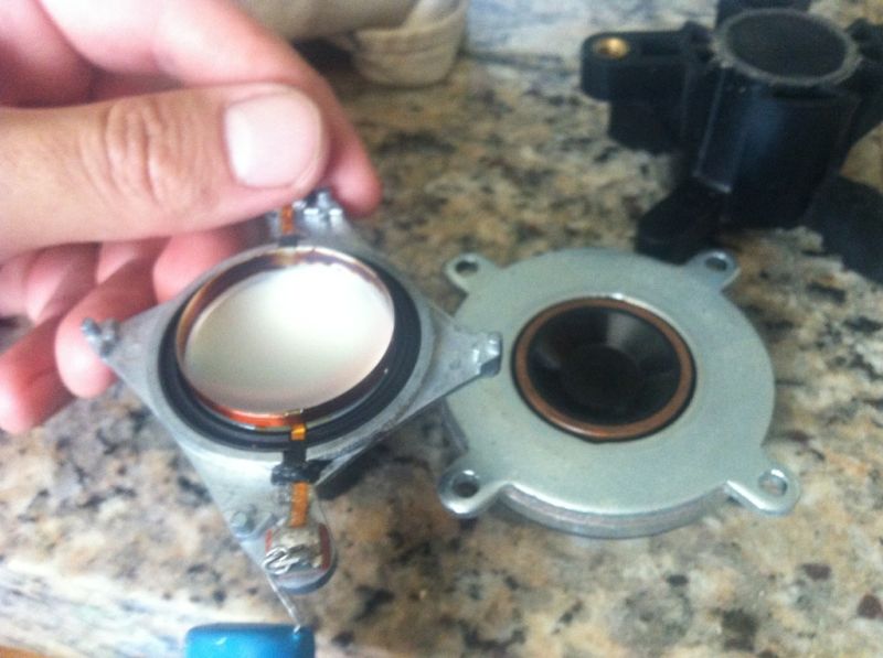
Here is a picture of a Celestion CDX1-1425 with and without the phase plug removed, and a picture of the phase plug itself. (The phase plug inserts inside a frustum, and forms the phase plug)
Here's an illustration that I made of the wavefront that's coming off of a CDX1-1425 when loaded on it's phase plug, and when loaded with it's phase plug on a Paraline. The hemispherical shape at the bottom of the illustration is the compression driver's dome. The arrows indicate the pathlength of sound radiating from the center and the edge of the dome. The funky yellow and purple checkerboard is there to make it easier for you to visualize the pathlength difference. Each square in the checkerboard is 0.5cm square.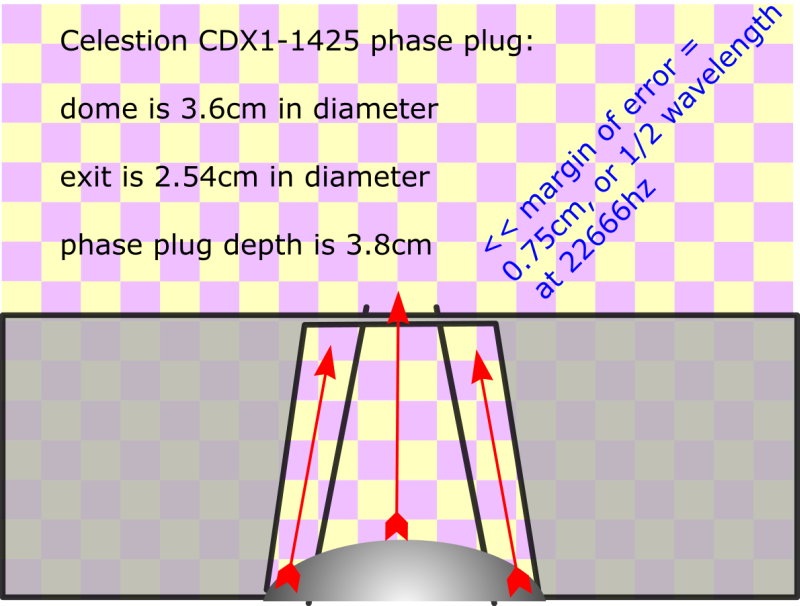

From my phase plug thread (http://www.diyaudio.com/forums/multi-way/219130-illustrated-demonstration-effect-phase-plugs.html), you'll recall that the sound of two radiators will null each other out when they're out of phase by one-half wavelength. I've coined a term for our phase plugs that I'll call our "margin of error." The margin of error is the distance at which the two radiators null each other out perfectly.
In the pic above, we see that the top of the Celestion's dome is about 0.75cm higher than the edge. This means that the sound from the top of the dome will reach your ears sooner than the sound from the edge. The phase plug on the Celestion is a simple frustum (Frustum - Wikipedia, the free encyclopedia). The frustum simply takes the energy radiated off of the diaphragm and focuses it into an area that's 2.54cm in diameter. Very simple.
We can calculate when the null will happen. Here's the formula:
speed of sound / distance / 2 =
34000cm per second / 0.75cm / 2
= 22666hz
So the pathlength difference between the tip of the dome and the edge of the dome should cause a null at approximately 22666hz. (This is just based on the phase plug, not on the Paraline.)
When we add the Paraline, the margin of error grows to about 1.75cm. If this doesn't make sense, just measure the length of the pathlength on the outside of the Paraline, then subtract the pathlength of the INSIDE of the Paraline.
In the pic I've posted above, of a 10cm Paraline, the pathlength difference is 1cm.
Using our formula again, we find that a difference of 1.75 gives us an upper limit of 9714hz. (1cm from the Paraline and 0.75cm from the phase plug of the Celestion itself.)
As Nate Hansen found, the margin of error of a plain ol' dome isn't much worse than this; for instance a 2.54cm dome has a margin of error of about 2.27cm (1.27 for the dome, 1cm for the Paraline) and it's upper limit is about 7488hz.
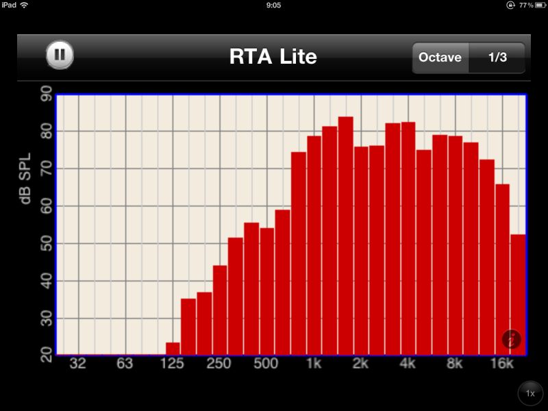
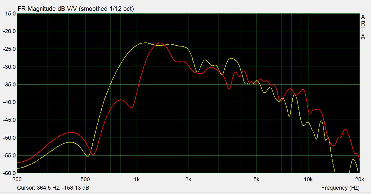
Here's a measurement of the CDX1-1425 on a Paraline. (I measured this using a simple RTA program for the iPad.)
In the graph, we see the high frequencies slowly rolling off beginning about 10khz. This isn't a 100% match with our predictions. But I think it's relatively consistent. I believe the reason that the null isn't as deep and obvious as what we see with a conventional phase plug is that the Paraline has a LOT of pathlengths. I believe this is spreading out the effect over the entire top octave. This may also explain why Nate's measurements show a series of notches:
Let me know if you have any questions about the nulls, why it happens, the geometry, etc.
At this point, you're likely wondering what will happen in the Y axis. I'll document that shortly.
In a recent post (quoted above) I argued that the Paraline is basically a phase plug. It's designed to equalize the pathlengths from the diaphragm of the radiator to the mouth of the horn
In the post above, I showed how it does this in the cross-section. In the cross section, I would argue that your uppper frequency limit is largely imposed by the height of the Paraline, the accuracy of the phase plug on the compression driver, and the dimensions of the radiator that's driving the whole thing. (I would argue that you have to include the phase plug of the compression driver as part of the greater whole; you can't assume that the compression driver is producing a perfectly flat disc shaped wavefront.)
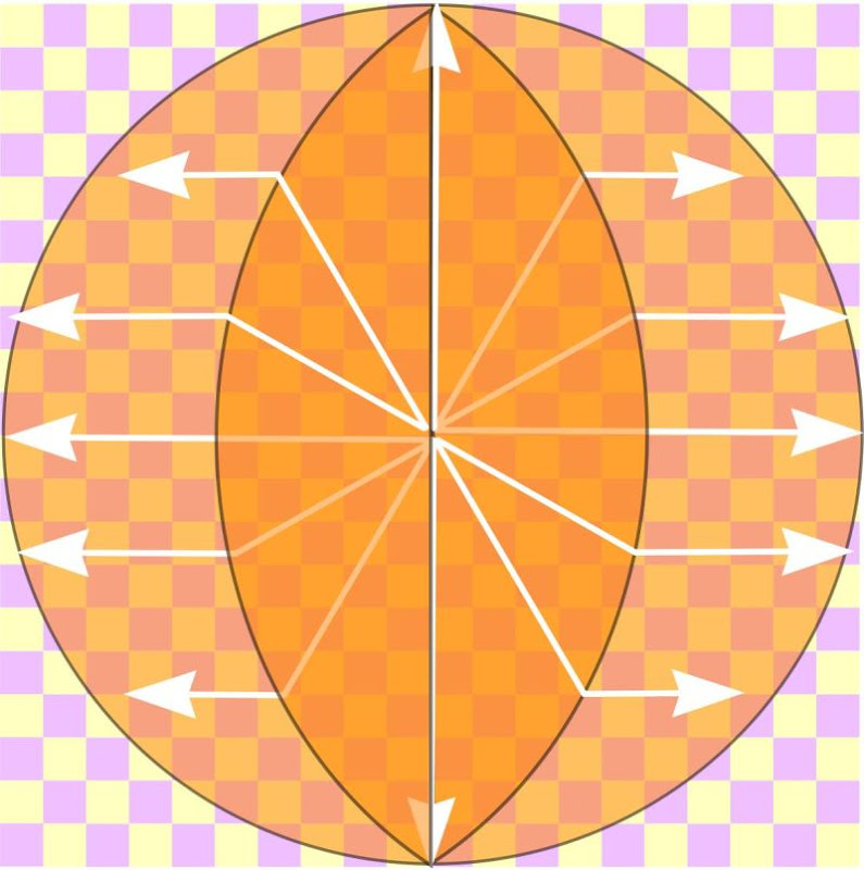
Here's an illustration of what the Paraline is doing, from overhead.
We see the following:
- The sound is radiating in 360 degrees, expanding in a series of concentric rings. This is why it acts like a conical horn; each 'ring' is larger than the last. So even though the cross section is equal in height, the area is expanding at every centimeter that we get further from the apex.
- The circular ring is folded over. The circular ring is cut in half. The first of two halves is an 'eye' shaped cut-out, 'scooped out' of the circle. This 'eye' shape dictates the shape of our Paraline.
- The second half of the Paraline has the same area as the first half. (The area of the first and second layers are equal.) But the wavefront is bent 90 degrees, due to the reflector between the first and second halves (see the patent.) This is why the wavefront bends at the boundary between the first and second half.
An externally hosted image should be here but it was not working when we last tested it.
If you look at my pic, you'll notice it isn't 100% perfect. It's flawless at 12 o'clock, 3 o'clock, 6'oclock and 9 o'clock. But it's iffy at 1 o'clock, 4 o'clock, etc.
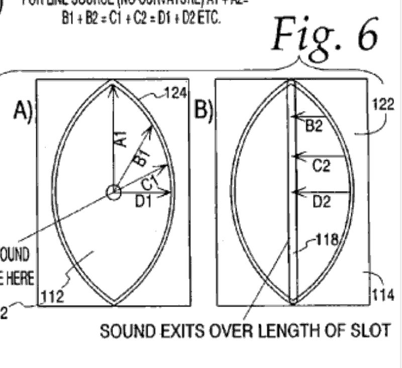
Looks like I have to fire up the ol' calculator, and solve the shape of the eye. We can calculate every point on 'the eye' because D1 + D2 always equals A1, and B1 + B2 always equals A1, etc...
Last edited:
First looking at Patrick's "Squaraline" and how it was folded I was under the impression that a paraline's folding was similar. This picture shows what was in my head.
Folding the outer edge of the circle towards the center then joining the two folds to create the eye shape.
The issue I encountered is the line down the center of the eye does not equal the diameter of the circle.
This pic that Patrick has posted begins to make more sense.
Thanks for posting Patrick.
The path length is still the tricky part. Maintaining an equal/close to equal path length between the outer and inner path is the hard part. On top of that, the addition of reflectors and phase plugs complicate matter all the more. Even with CAD software, I'm still scratching my head.
None the less I'm still giving it the ol' college try.
Looks like I have to fire up the ol' calculator, and solve the shape of the eye. We can calculate every point on 'the eye' because D1 + D2 always equals A1, and B1 + B2 always equals A1, etc...
Patrick - I think the shape of one half of the eye is part of a circle, the radius of which is 2.5 x D1. So 12.5 blocks in your example above.
The shape of each half of the eye is a parabola with focus at the driver center. It's the only shape I know of that can take a spherical wave and make it a planar wave, all in phase, with a single specular reflection.
This now makes PERFECT sense.
Here is a diagram:

All the line segments that coincide are equal in pathlength.
The paraline exit is a line horiontal through the focus, and the focus is where the driver inserts. Very elegant.
JSS
This now makes PERFECT sense.
Here is a diagram:
All the line segments that coincide are equal in pathlength.
The paraline exit is a line horiontal through the focus, and the focus is where the driver inserts. Very elegant.
JSS
Does the path length always have to be the same? If we're looking to build arrayable modules like the VTC stuff I could see keeping a super narrow vertical window, but for home use I want a bit more directivity than that. There was talk earlier in the thread about "pinching" the center of the eye in effect creating a time delay and increasing the vertical dispersion. Conversely you could widen the center and get a pattern that actually narrows. I think I can "see" how this works in my head, but can't really explain it. Or am I just making stuff up.....I built my 'lines based on Bateman's spreadsheet for 40deg vertical dispersion. I'll see if I can't get it rigged up on my rotary table and get some polars.
Yes.
If you make the sides of the eye a hyperbola with one focus being the driver position, the reflection from the eye will be a 'circular' wave with curvature equal to how far away the other hyperbolic focus is.
If you make the sides of the eye elliptical, with the long side of the eye the minor axis through a focus, and the driver at the focus, the reflection off of the eye will converge in phase (circular wavefront) to the other focus of the ellipse, making a converging wavefront.
With a few equations, you can customize one of these things to focus, spread, or project straight away.
The pretty cool part of the diverging/converging wavefront would be that it is already power tapered, so it will act like a CBT, and not have any vertical lobing.
The coolest thing about this device is the fact that it constrains the sound within such a small chamber that it can be treated almost optically/specularly, and use simple conic sections to do what you need.
The problems with this are driver size/driver opening size. You can have pathlength differences significant enough to cause cancellation if your driver opening starts to get large compared to the max wavelength possible constrained by the plate thicknesses. I would suggest using smaller driver openings if possible to avoid this, provided it doesn't cause other problems. Of course a point source and paper-thin plates would be ideal, but not possible.
JSS
Last edited:
Busted out the rusty geometry skills and made the attached spreadsheet. Not sure if it's right but here is my line of reasoning:
Let "theta" be the angle between the reference axis (the paraline "slit") and the rays like A1, B1, C1 etc. Lets use the variable "H" for the length of rays like A1, B1, C1 etc coming immediately out of the compression driver. Lets use the variable "X" for the length of the lines returning to the centerline after bending around the eye (A2, B2, C2 etc). Finally, lets call L half the width of the narrow dimension of the eye (you pick it to be whatever size you want).
First of all, we want to set H+X=2L because we want the wavefront to arive at the front slit all at the same time or distance.
We also know that Hsin (theta)=X or after some algebra, H=X/sin(theta). This is because, with driver at the origin, the wave propagates radially (the H ray, or hypotenuse), bends around the eye, and heads towards, and normal to, the center slit (the X path). This creates a sort of "right triangle" geometry.
Substituting the latter into the first and manipulating algebraically yields X(1+1/sin(theta))=2L.
Finally, after some more manipulation, X=2L/(1+(1/sin(theta))), where X is the distance from the curve normal to the reference axis (like A2, B2, C2 etc).
To get the corresponding cartesian coordinate, take X/tan(theta)=Y.
There is probably a way to do it totally in a cartesian system without messing with the polar calcs (ie, no trig functions), but I'll leave that to someone else. And you might find that it is really a hyperbola, but I just constrained the curve to what we know & want.
All of this assumes the "vanilla" version of the eye with a 2:1 aspect ratio. No phasing/focusing as a few of you have discussed. For that you're on your own.
By all means, correct me if my math is wrong.
Cheers,
Sam
Attachments
Last edited:
The problems with this are driver size/driver opening size. You can have pathlength differences significant enough to cause cancellation if your driver opening starts to get large compared to the max wavelength possible constrained by the plate thicknesses. I would suggest using smaller driver openings if possible to avoid this, provided it doesn't cause other problems. Of course a point source and paper-thin plates would be ideal, but not possible.
JSS
B&C sells compression drivers with 0.5" and 0.7" exits.
hmmm...
Here's a review from Voice Coil : http://read.uberflip.com/i/34611/13#
Jason Winslow has some of these I believe
Last edited:
Use a Paraline instead of a 2" driver
First of all I want to thank Tom Danley for his generousity with the DIY crowd. Thanks a lot to you other guys explaining (and using ages to produce drawings) to help us understand the inner workings of yet another clever device from TD.
Before I plunge into a full Synergy project, I would like to play with the Paraline device. And looking in my basement I could not miss two huge horns looking for a decent driver. My JBL 2360 horn consists of two parts. The throatpiece has a 2" entry. The main horn has an entry of 18x252 mm and the mouth is 80x80 cm with 90x50 coverage. What if I substituted the throatpiece for a Paraline?
Having looked around for a 2" driver, my main candidates has been JBL 2452/2446/Radian 950 with Truextent or a BMS coax. But with some patience, a lot of tinkering, measuring and listening, maybe I could end up with a Paraline that has both a more extended low and high frequency than my 2" options.
With any 2" I would need a supertweeter wich are difficult to integrate. With a Paraline there are lots of options. I really liked Patrick Batemans design with a mid/midwoofer behind the tweeter.
The problems with this are driver size/driver opening size. You can have pathlength differences significant enough to cause cancellation if your driver opening starts to get large compared to the max wavelength possible constrained by the plate thicknesses. I would suggest using smaller driver openings if possible to avoid this, provided it doesn't cause other problems. Of course a point source and paper-thin plates would be ideal, but not possible.
JSS
I guess some of this is covered in the Synergy threads, regarding getting the midrange holes small enough. I understand this is helped by using frustums. Because its the midrange holes that present the biggest hypothetical problem?
FLH has loads of hands-on experience with this and his Paraline build uses a curved opening for the midrange that at least looks a bit wide for the wavelengths involved. So I guess you could get away with it. Have to try it myself.
Patrick Batemans idea of using a mid/midwoofer behind the tweeter in post
http://www.diyaudio.com/forums/multi-way/217298-square-pegs-16.html#post3143329 looks really clever. Having the mid symmetrically around the tweeter, is it possible to use several smaller openings to get the desired area?
- Home
- Loudspeakers
- Multi-Way
- Square Pegs