Don,
You are correct about the different things we are looking at here. I don't think that the path length differences are that great with the curved or straight cut corners, but I do question what the square corners are doing with reversion waves in the current design with square corners.
You are correct about the different things we are looking at here. I don't think that the path length differences are that great with the curved or straight cut corners, but I do question what the square corners are doing with reversion waves in the current design with square corners.
Speed of sound ~ 13492.48 inches per second at STP&H@SL. We need to stay 1/3 a wavelength or smaller. If we divide the speed of sound by 3 and then by 0.25" we'll get the highest frequency the paraline should play to.
13492.48/3/0.25 = 17989.97Hz
Therefore a paraline constructed from 0.25" material should be good to almost 18KHz. That's why John and I have been using 0.25" or thinner material. Despite the small dimensions, having reflectors along the diagonal will benefit the high frequency performance. Huygen's Wavefront Construction Principle has held true for all the folded horns I've ever built. Dr. Edgar got this right. The paraline will be no different, it just needs to be sized for the wavelengths involved.
That being said, the square corners will only present a minimal issue if the correct material thickness is used. The physics of the situation precludes it from being a major problem because the wavelengths are too large in relation to the square corner's acoustical image size.
One only needs to exercise common sense for the physics at hand to build a very well performing paraline. Its not that difficult.
Attachments
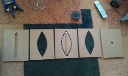
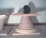
I built a Paraline this weekend, and did some quick and dirty testing today. I dimensioned it using Bateman's spreadsheet for 40 deg vertical dispersion, so its "pinched." I'm not much of a wood worker, more of a hack really, but I put a lot of effort into getting these things right. I made the "eye cutout" pieces with 45 deg angles because the abrupt 90 deg corners were bothering me. Unfortunately I made that decision an hour and a half away from my computer and CAD software, so I had to remake the template on the fly. I think it came out ok.
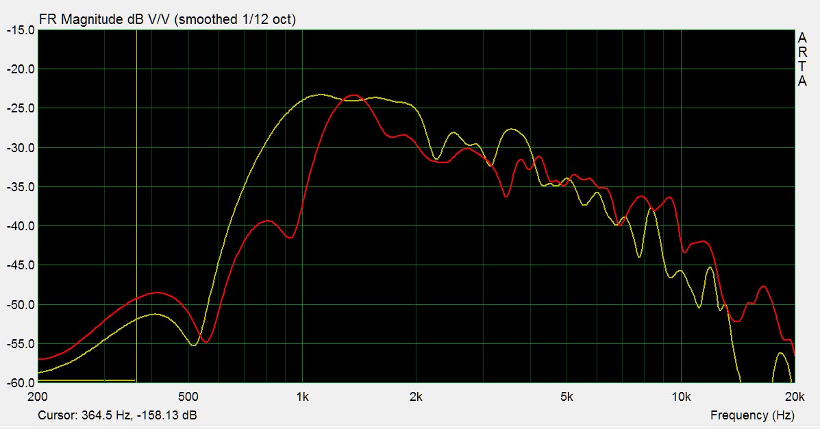
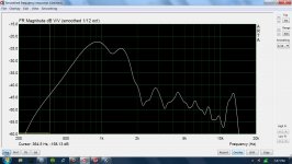
I was eager to see if it worked, so I put a 1" dome tweeter over the 1" hole for the comp driver. This was pretty sketchy, because the dome has a chamfer on its faceplate that the dome recesses into, so I was effectively creating a chamber for the dome. The yellow line is the measurement. I haven't yet made a reflector for the hf driver throat. Measuring with and without the mouth reflector showed that I got me a little smoother hf, with a tad more extension. Either way, I think I'm running into what Don is talking about with the path-length differences. Obviously this thing is low-passing the tweeter. My pathlength difference in the bend (with my angled path) comes out to about .375", which works out to about 12k at 1/3 wl.
I thought that maybe the chamber created by the dome on my driver mount plate was doing the filtering, so I quick rigged up a piece of cardboard with a hole large enough for the tweeter dome to protrude through (I took the faceplate off). That's the red measurement. A bit more extension and less bottom end.
Obviously this setup with the dome is far from optimal, but it'll be interesting to see how the comp driver performs once I get it.
Attachments
Last edited:
You are correct about the different things we are looking at here. I don't think that the path length differences are that great with the curved or straight cut corners, but I do question what the square corners are doing with reversion waves in the current design with square corners.
I wondered that myself, but the general wisdom is that provided the width (not the length) of the duct is significantly smaller than the wavelength, the corners will have no significant effect. The wave models used in Hornresp / Ripple show this, and you can bet that Tom Danley has proved it in real life physical models. If I had doubts, I could prove it to my own satisfaction in a few hours with two lengths of 1" PVC electrical conduit, one straight, the other with one or more right-angle bends (conduit elbows) in it. Feed the signal from a small driver into each in turn, put a microphone at the other end, run a sweep over the 500 Hz to 5 KHz range. Compare the results. They should be very similar up to about 2 or 3 KHz. (1" pipe = 2" difference at a 90 degree bend = 1/3 wavelength = 6 inch wavelength = 2250 Hz)
Last edited:
Speed of sound ~ 13492.48 inches per second at STP&H@SL. We need to stay 1/3 a wavelength or smaller. If we divide the speed of sound by 3 and then by 0.25" we'll get the highest frequency the paraline should play to.
13492.48/3/0.25 = 17989.97Hz
Therefore a paraline constructed from 0.25" material should be good to almost 18KHz.
That's the part I question, because the patent only mentions 1/3 wavelength when it discusses the path length in the bends. Paragraph [0034] in the patent. In summary, if the horn is folded, the highest frequency for smooth response is half of that implied by the wall spacing. Above that frequency, the response will progressively drop off due to the inductive effect of the bends.
Tom, are you following this? Did you choose the 1/3 wavelength figure from prior art as implied in the patent, or from actual measurements?
I'm not going to speak for Tom, but we all know that at 1/2 wavelength we WILL get a cancellation. We also know that very few bad things happen when we are at 1/4 wavelength. I believe that the 1/3 wavelength comes from the bare minimum needed to avoid cancellation issues.
I was eager to see if it worked, so I put a 1" dome tweeter over the 1" hole for the comp driver. This was pretty sketchy, because the dome has a chamfer on its faceplate that the dome recesses into, so I was effectively creating a chamber for the dome. The yellow line is the measurement. I haven't yet made a reflector for the hf driver throat. Measuring with and without the mouth reflector showed that I got me a little smoother hf, with a tad more extension. Either way, I think I'm running into what Don is talking about with the path-length differences. Obviously this thing is low-passing the tweeter. My pathlength difference in the bend (with my angled path) comes out to about .375", which works out to about 12k at 1/3 wl.
I thought that maybe the chamber created by the dome on my driver mount plate was doing the filtering, so I quick rigged up a piece of cardboard with a hole large enough for the tweeter dome to protrude through (I took the faceplate off). That's the red measurement. A bit more extension and less bottom end.
Obviously this setup with the dome is far from optimal, but it'll be interesting to see how the comp driver performs once I get it.
Actually your results are pretty good. Like any conical horn, we're going to see a lot more gain on the low end.
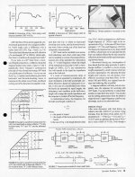
Here's a graph that John Krutke made, horn loading a dome tweeter on a Parts Express waveguide.
See the big swings in output that John is getting at the top end? That's what we DON'T want.
A big bump at the low end, and a smooth rollof is what we *do* want. A graph like yours is easy to flatten using standard filters. The thing we want to avoid are peaks followed by dips. Which is what we get when the pathlengths are wrong. The Dayton 2" dome exhibits this problem, and so does the BG NEO 8.
But I don't see that prob in your graph.
Exciting stuff!
I built a Paraline this weekend, and did some quick and dirty testing today. I dimensioned it using Bateman's spreadsheet for 40 deg vertical dispersion, so its "pinched." I'm not much of a wood worker, more of a hack really, but I put a lot of effort into getting these things right. I made the "eye cutout" pieces with 45 deg angles because the abrupt 90 deg corners were bothering me. Unfortunately I made that decision an hour and a half away from my computer and CAD software, so I had to remake the template on the fly. I think it came out ok.
I was eager to see if it worked, so I put a 1" dome tweeter over the 1" hole for the comp driver. This was pretty sketchy, because the dome has a chamfer on its faceplate that the dome recesses into, so I was effectively creating a chamber for the dome. The yellow line is the measurement. I haven't yet made a reflector for the hf driver throat. Measuring with and without the mouth reflector showed that I got me a little smoother hf, with a tad more extension. Either way, I think I'm running into what Don is talking about with the path-length differences. Obviously this thing is low-passing the tweeter. My pathlength difference in the bend (with my angled path) comes out to about .375", which works out to about 12k at 1/3 wl.
I thought that maybe the chamber created by the dome on my driver mount plate was doing the filtering, so I quick rigged up a piece of cardboard with a hole large enough for the tweeter dome to protrude through (I took the faceplate off). That's the red measurement. A bit more extension and less bottom end.
Obviously this setup with the dome is far from optimal, but it'll be interesting to see how the comp driver performs once I get it.
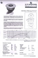
I need to compliment you on your workmanship, well done. Your measurements are much better than you might think. I've played with horn loading Dynaudio soft dome midranges and tweeters like Dr. Edgar did back in the day. These kind of drivers are not really appropriate for horn loading applications. They always rolloff because they lack the motor strength to over come the dome mass at the high end. They are not compression drivers. We also must remember that the radial expansion of the paraline approximates a conical horn. That means it will have a falling high frequency response. Your measurements show a high frequency rolloff, but I would have expected it to be much worse. Quite honestly, what you have there is very good for the limitations you have in play.
Attachments
Last edited:
So. A Paraline constructed of 1/4" material. Highest frequency 9 KHz or 18 KHz?
Just look at the Danley paraline and that should be obvious.
I need to compliment you on your workmanship, well done. Your measurements are much better than you might think.
Thanks! I gotta say my pic makes them look nicer than they are though.
I was expecting the top end to roll off, but 20db seemed a bit much. Like you say though, a dome isn't exactly a comp driver. I'm not a horn guy and I've never used a compression driver so this is uncharted territory for me.
I wanted to see how a mid performed on the Paraline, and the closest candidate I had was a Fountek FR88 fullranger. I used plumber's putty to seal up the basket, and also to seal it to the throat plate. Graph included.
I eq'd it flat within its bandwidth, then redid the crossover on my Neo8's (the upper mids of my 4-way dipoles) to match the FR88 and listened. The Neo sounded dull and lifeless compared to the Paraline. I guess this is the dynamics you guys keep on about
 . Then I whipped up a ghetto waveguide out of cardboard and duct tape for the Paraline and listened some more. Very promising! Despite the limited bandwidth and obviously very wrong cardboard waveguide I really like what I was hearing. Definitely potential here.
Attachments
Last edited:
JLH/PB,
I can conceptually see the conical horn approximation from driver to 'edge' of paraline upon which the wave either doubles back and quicklyexits (ends of line) or doubles back and travels some distance prior to exit (i do understand that pathlengths can be adjusted by the width of the eye). During the longer double-backs, does the horn 'area' keep expanding, or is the 'area' getting smaller until the wave hits the 90 degree reflector at the mouth?
I just need to unfold it in my head. A pic/animation here is literally worth a thousand words.
Great experimentation going on here with a very novel and interesting idea from TD...
JSS
I wanted to see how a mid performed on the Paraline, and the closest candidate I had was a Fountek FR88 fullranger. I used plumber's putty to seal up the basket, and also to seal it to the throat plate. Graph included.
I eq'd it flat within its bandwidth, then redid the crossover on my Neo8's (the upper mids of my 4-way dipoles) to match the FR88 and listened. The Neo sounded dull and lifeless compared to the Paraline. I guess this is the dynamics you guys keep on about
Unity horns give you the point source radiation of a Lowther, with potentially better directivity and bandwidth.
This is why I've been a lunatic about them for a decade now
https://www.google.com/#hl=en&sclient=psy-ab&q="patrick+bateman"+unity
... We also must remember that the radial expansion of the paraline approximates a conical horn. ...
??? I thought it was parabolic.
For a Paraline (or its unfolded equivalent), the mouth area for a given length (radius) is pi * diameter * slot width. Double the length (radius), double the area.
For an axisymmetrical conical horn, the mouth area for a given length is pi * radius squared. Double the length, quadruple the area.
It seems counterintuitive to me... what am I missing?
The key word here guys is "approximates". I know several of us on here are very detailed and analytically minded, but we need to keep this stuff in perspective. I've built so many things I have a feel for what is important and what can be stretched a little bit. My grandfather, whom was a master machinist for Ford Motor Company, had a saying for when people became overly anal-retentive about details. He would tell these people, “Yes you can go ahead and do that, but it’s like picking fly s*** out of pepper”.
Thanks! I gotta say my pic makes them look nicer than they are though.
I was expecting the top end to roll off, but 20db seemed a bit much. Like you say though, a dome isn't exactly a comp driver. I'm not a horn guy and I've never used a compression driver so this is uncharted territory for me.
I wanted to see how a mid performed on the Paraline, and the closest candidate I had was a Fountek FR88 fullranger. I used plumber's putty to seal up the basket, and also to seal it to the throat plate. Graph included.
I eq'd it flat within its bandwidth, then redid the crossover on my Neo8's (the upper mids of my 4-way dipoles) to match the FR88 and listened. The Neo sounded dull and lifeless compared to the Paraline. I guess this is the dynamics you guys keep on about
As your measurement indicates, you made the mass rolloff even worse by placing a midrange onto the paraline. Being down 20dB with a dome tweeter is quite good. Even a compression driver is down a good 10dB most of the time.
JLH/PB,
I can conceptually see the conical horn approximation from driver to 'edge' of paraline upon which the wave either doubles back and quicklyexits (ends of line) or doubles back and travels some distance prior to exit (i do understand that pathlengths can be adjusted by the width of the eye). During the longer double-backs, does the horn 'area' keep expanding, or is the 'area' getting smaller until the wave hits the 90 degree reflector at the mouth?
I just need to unfold it in my head. A pic/animation here is literally worth a thousand words.
Great experimentation going on here with a very novel and interesting idea from TD...
JSS
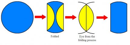
It’s always expanding. It is a circle that has two parallel sides folded over. There is no limit to how many times you fold up the sides of the circle. Instead of a single fold like in my attached picture, you can fold the sides into a Z shape.
Attachments
- Home
- Loudspeakers
- Multi-Way
- Square Pegs