If you measure from the driver to the nearest part of the mouth, the path length is the same all around the line - all parts of the wavefront from the driver arrive at the mouth at the same time.
I don't see how this can hold true. If the distance from the source is the same length at all points it would seem that the wavefront must be on a curve not a straight vertical line.
And furthermore, if the "no waves form inside" theory actually works this should also be a HOM / diffraction free horn.
I would argue that this is a diffraction lens. The vertical dispersion is controlled by the height being equal to the longest wavelength giving no diffraction. The narrow slit is working just the opposite and the horizontal dispersion is completely realized through a diffraction affect. This is a diffraction lens if I ever saw one.
Well, I've joined the Paraline club. It is using a Selenium D220TI and a pair of Misco RDC3TA 3" mids. I still need to sand and file some rough spots down before doing the final assembly, but the bulk of the work is done. I have the crossover written down on paper, but I know it will need a little tweaking. It wasn't bad at all building the Paraline. This is SO MUCH EASIER than building conical horn shells. Unless something unforeseen screws this up, this is the only way to build Unity/Synergy horn in my opinion.
An externally hosted image should be here but it was not working when we last tested it.
If you measure from the driver to the nearest part of the mouth, the path length is the same all around the line - all parts of the wavefront from the driver arrive at the mouth at the same time.
I don't see how this can hold true. If the distance from the source is the same length at all points it would seem that the wavefront must be on a curve not a straight vertical line. ...
It's easy to prove it is true. Like I said, measure out from the driver to the "eye" shaped slot, then from the slot to the nearest part of the mouth. Repeat this for any direction out from the driver. Patrick posted a video which demonstrated this with a piece of string.
Last edited:
Well, I've joined the Paraline club. ...
I have my doubts about the effectiveness of the mid drivers. The geometry is dubious - there is no clearly defined position of the drivers in the line. It's a bit like making the midrange openings in a Synergy horn into longitudinal slots instead of round holes. Also, did you calculate the line length to be long enough for the lower cutoff frequency of the mids? It only looks big enough for the tweeter.
I have my doubts about the effectiveness of the mid drivers. The geometry is dubious - there is no clearly defined position of the drivers in the line. It's a bit like making the midrange openings in a Synergy horn into longitudinal slots instead of round holes. Also, did you calculate the line length to be long enough for the lower cutoff frequency of the mids? It only looks big enough for the tweeter.
I addressed all the above concerns during the design process. The details how to add mids to the paraline was clearly covered in the patent. Placement of the mids is also much more forgiving due to the longer wavelengths involved. The acoustic path length of the compression driver along with the distance where the mids tap in were accounted for in my paraline. I've been doing this stuff for a while now. This isn't my first build. I just don't understand all the pessimism around the paraline. I remember the hostility the original Unity horn received when it was first released. I had hoped we were past this kind of negative mindset.
The patent's midrange arrangement is quite different, with the ports much closer to the apex. (Fig 9). The further out the ports are, the greater the difference will be between the HF and MF dispersion patterns at the crossover point, and there's a body of opinion that says they should be matched if possible. If you don't subscribe to that argument then no problem...
I'm not against the Paraline. Quite the opposite. My concerns are that modifications made without an understanding of the operating principles may result in disappointment through no fault of the Paraline's design principles, as happened with the Unity horn.
That's not a criticism of your skills. I just expressed my opinion.
The patent's midrange arrangement is quite different, with the ports much closer to the apex. (Fig 9). The further out the ports are, the greater the difference will be between the HF and MF dispersion patterns at the crossover point, and there's a body of opinion that says they should be matched if possible. If you don't subscribe to that argument then no problem...
I'm not against the Paraline. Quite the opposite. My concerns are that modifications made without an understanding of the operating principles may result in disappointment through no fault of the Paraline's design principles, as happened with the Unity horn.
That's not a criticism of your skills. I just expressed my opinion.
Fair enough. How much weight do we give to the dispersion pattern at the crossover point? Looking at the current speaker offerings using the paraline, the mids are not even mounted to the paraline; they're on the horn shell. Having the mids closer to the compression driver and mounting them on the paraline would further minimize this disparity rendering it a moot point. The advantage I see in the paraline is in its radial expansion. This eliminates a lot of problems with midrange placement. If we zoom out and take a more elementary look at the paraline, its just a bifurcated radially expanding horn. If treated as such, and we apply the additional tidbits given in the patent it is a fairly straight forward process.
Looks like a very clean piece of work.Unless something unforeseen screws this up, this is the only way to build Unity/Synergy horn in my opinion.
I am very curious as to whether the sharing of a throat may cause intermodulation distortion of the HF driver from the mid drivers.
This is no problem in the Unity/Synergy horn, but your placement is far more "communal".
If you have an RTA, a screenshot of the product of 300 Hz (or whatever the low end of the mid driver is) at a peak operating level and an uneven HF frequency (like 1525 Hz) would be interesting.
Hi,
some questions about the paraline, I can't wrap my head around these matters:
- the diameter of the exit slot still dictates the cut-off frequency, right? In the case of the eye shaped, the cut-off frequency should then be dictated by the length of the slot. That is, if an unfolded horn would have a mouth of 12" then the equivalent paraline would have the same exit slot?
- is the paraline also exhibiting any gain, as a traditional horn?
Thanks!
Not sure if that would be the case, the area were the signals are mixing is still an area of laminar flow. I believe that in some ways it's the same as the compression chambers of the coaxial drivers from BMS.
On the other hand, the distance from the CD exit to the exit slot is optimized while in the case of the midranges is not. And this would mean different wavefronts for the CD and midrange drivers..
some questions about the paraline, I can't wrap my head around these matters:
- the diameter of the exit slot still dictates the cut-off frequency, right? In the case of the eye shaped, the cut-off frequency should then be dictated by the length of the slot. That is, if an unfolded horn would have a mouth of 12" then the equivalent paraline would have the same exit slot?
- is the paraline also exhibiting any gain, as a traditional horn?
Thanks!
I am very curious as to whether the sharing of a throat may cause intermodulation distortion of the HF driver from the mid drivers.
Not sure if that would be the case, the area were the signals are mixing is still an area of laminar flow. I believe that in some ways it's the same as the compression chambers of the coaxial drivers from BMS.
On the other hand, the distance from the CD exit to the exit slot is optimized while in the case of the midranges is not. And this would mean different wavefronts for the CD and midrange drivers..
If you measure from the driver to the nearest part of the mouth, the path length is the same all around the line - all parts of the wavefront from the driver arrive at the mouth at the same time.
I don't see how this can hold true. If the distance from the source is the same length at all points it would seem that the wavefront must be on a curve not a straight vertical line.
And furthermore, if the "no waves form inside" theory actually works this should also be a HOM / diffraction free horn.
I would argue that this is a diffraction lens. The vertical dispersion is controlled by the height being equal to the longest wavelength giving no diffraction. The narrow slit is working just the opposite and the horizontal dispersion is completely realized through a diffraction affect. This is a diffraction lens if I ever saw one.
You've made an excellent observation. There *are* similarities between the VTC Paraline designs and diffraction horns like the old Mantaray designs. Both are two-stage designs. (a horn feeding a horn)
Thankfully, we know an airtight solution to the diffraction problem. That solution is to minimize or eliminate the discontinuity between the two horns.
For instance, when Geddes builds his OS waveguides he factors in the exit angle of the compression driver. By doing this, Geddes creates the gentlest possible transition from one segment to the other.
We can do the same thing in a Paraline - we just have to be conscious of the expansion rate and avoid any abrupt changes.
In the VTC boxes it might appear that there's an abrupt shift in the expansion rate at the point where the Paraline mates with the horn. But this isn't necessarily true. The Paraline expands in a 360 degrees, so the coverage angle is an average of 180 degrees. ((360 horizontal + 0 degrees vertical) / 2). The Paraline then enters a horn that's 90 by 15 degrees, or an average of 52.5 degrees.
Of course, the easiest way to compare a Paraline to a diffraction horn would be to examine the expansion rate along the entire length of the horn. I'd argue that you'd see an abrupt increase in the expansion rate of the Manta Ray horn, but not in the VTC boxes.
All of the above comments would make a lot more sense if I included pics. The key to all of this is that the sound is expanding 360 degrees in a Paraline, which allows for a surprisingly fast expansion rate, despite the very shallow height of the horn.
I have some of the mids...and the neo version of that compression driver.
What kind of bandrange are you going to be running those guys at John? Would adding another mid to make 3 per side do anything significant?
I did love the litte Unities that I came up with.
I'm looking to run the RDC3TA from 300Hz to about 1.9KHz. You could run as many mids as you want. You just have to keep them equal distant from the compression driver entrance because we are dealing with a radially expanding wave. The next thing you'd have to do is size the paraline such that you can fit them on there. Due to the shape of the paraline, two mids are a natural choice. That's what I decided to stick with. A pair of the RDC3TAs are capable of more than enough SPL for home use so I didn't see the need for more.
Looks like a very clean piece of work.
I am very curious as to whether the sharing of a throat may cause intermodulation distortion of the HF driver from the mid drivers.
This is no problem in the Unity/Synergy horn, but your placement is far more "communal".
If you have an RTA, a screenshot of the product of 300 Hz (or whatever the low end of the mid driver is) at a peak operating level and an uneven HF frequency (like 1525 Hz) would be interesting.
I don't see how the paraline is any different than a normal Unity or Synergy horn. The paraline is basically a bifurcated horn at the throat. From the individual driver's view point, it should look like a normal Synergy horn with a center brace placed into the throat.
Attachments
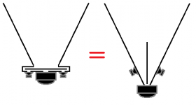
The Paraline as drawn on the left exposes the HF driver to a much higher pressure zone created by the mid drivers than the off set driver approach on the right.I don't see how the paraline is any different than a normal Unity or Synergy horn. The paraline is basically a bifurcated horn at the throat. From the individual driver's view point, it should look like a normal Synergy horn with a center brace placed into the throat.
Normally the exit would be only 1 inch wide (not 4 or 5 as drawn) to allow for decent HF dispersion, if drawn normally it would be more easy to see the difference.
As posted previously, the throat SPL in a driver is quite high, for instance at the horn mouth, 26” from the HF driver throat screen was 126.3 dBA, 143.7 dBA at the HF driver screen. Just 6.5" inches from the screen the level dropped to 136.8 dBA.
As an anecdotal indication of the potential problem, Dave Rat (Rat Sound, Red Hot Chili Peppers FOH engineer) found that he was shattering unpowered berrilium TAD HF diaphragms during testing of the front loaded mid cones which were tightly packed around the HF horn. Removing the series "protection" capacitors let amp damping keep the HF diaphragms in place. That said, the throat arrangement in your Paraline would be at least an order of magnitude more problematic than Dave's "Rat Trap" arrangement.
Whether sharing the high pressure end of the horn throat will make a difference or not in IM distortion can only be determined by testing, I will be interested in your findings.
Art
Last edited:
Hi Art
The TAD drivers are a bit unusual in that they generally have a very low (for a compression driver) resonant frequency and so the traditional series cap leaves them fully un-damped and easy for the diaphragm to move around.
What works much better is a driver with a higher Fs and more excursion capability and then using a parallel choke as the final element across the driver. This way instead of seeing an open circuit as the frequency falls, it sees a short and is highly damped and very hard for external pressure to move around.
I try to use that L as the majority of the compensation slope involved so they are typically a fairly small value as well. In some cases, the L is small enough to make the compression drivers impedance a non-issue as well as it dominates the crossover load..
Has it been unusually hot and dry in your neck of the woods (or desert) this year (like it has been here)?
The only upside is very few mosquitoes.
Best,
Tom
The Paraline as drawn on the left exposes the HF driver to a much higher pressure zone created by the mid drivers than the off set driver approach on the right.
Normally the exit would be only 1 inch wide (not 4 or 5 as drawn) to allow for decent HF dispersion, if drawn normally it would be more easy to see the difference.
As posted previously, the throat SPL in a driver is quite high, for instance at the horn mouth, 26” from the HF driver throat screen was 126.3 dBA, 143.7 dBA at the HF driver screen. Just 6.5" inches from the screen the level dropped to 136.8 dBA.
As an anecdotal indication of the potential problem, Dave Rat (Rat Sound, Red Hot Chili Peppers FOH engineer) found that he was shattering unpowered berrilium TAD HF diaphragms during testing of the front loaded mid cones which were tightly packed around the HF horn. Removing the series "protection" capacitors let amp damping keep the HF diaphragms in place. That said, the throat arrangement in your Paraline would be at least an order of magnitude more problematic than Dave's "Rat Trap" arrangement.
Whether sharing the high pressure end of the horn throat will make a difference or not in IM distortion can only be determined by testing, I will be interested in your findings.
Art
Good information Art, thanks! I'm very interested in what happens to this too. I won't know until it is properly tested, but I suspect it will be fine for home use. The RDC3T-A is a 3" cone tweeter, so I don't see it ever doing any damage to a decent compression driver. I also don't ever see myself pushing this thing past 105dB in its lifetime.
Last edited:
Short video of my paraline. Still need to do a few more things before finalizing it. I'll be adding the crossover in a little while. Then there's the need for a proper horn shell too.
Paraline build - YouTube
Paraline build - YouTube
Have you tried a fabric/epoxy prototype like Tom did on sh-100.
It sounds lika a fast and easy way to get a horn to try your paraline on.
He describes it here: http://www.diyaudio.com/forums/multi-way/72598-waveguide-ala-genelec-need-help-building.html
/Nils
It sounds lika a fast and easy way to get a horn to try your paraline on.
He describes it here: http://www.diyaudio.com/forums/multi-way/72598-waveguide-ala-genelec-need-help-building.html
/Nils
Have you tried a fabric/epoxy prototype like Tom did on sh-100.
It sounds lika a fast and easy way to get a horn to try your paraline on.
He describes it here: http://www.diyaudio.com/forums/multi-way/72598-waveguide-ala-genelec-need-help-building.html
/Nils
I already have the horn shell designed for this paraline. I just need to build it. That will be coming in the next few weeks. Building the paraline was a quick burst to get something done. I've had little time for audio projects, but the opportunity presented itself and I took advantage of it.
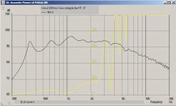
This is the reason (the graph below) why I went ahead and did a quick listen to the paraline without a crossover. This is the simulation of the paraline with the horn shell. Of course the horn shell has not been built yet, but I wanted to hear it anyway. This simulation has no crossover or high frequency compensation. It is just all three drivers being driven in parallel. The crossover should be pretty simple since the driver summation is so good to begin with.
Attachments
- Home
- Loudspeakers
- Multi-Way
- Square Pegs