moar pics :
An externally hosted image should be here but it was not working when we last tested it.
the real deal
two hour knockoff
smile!
... The extremely shallow depth of the BG drivers makes this do-able. ...
Using a NEO 8 like that won't work very well. The NEO 8 does not approximate a point source at the dimensions of your test Paraline. You have most of the back wall of the Paraline as a sound source. There will be a lot of cancellation and lobing. I suspect that's why you're getting HF loss.
It doesn't matter how long the wave has to travel to get to a bend, it is the dimensions of the bend itself that matter. In a "properly" designed paraline that bend is acoustically invisible to the wave front. The acoustical image size the bend presents is too small to effect the wave front traveling around it. However, almost everything you have stated holds true for frequencies above 18KHz in a 1/4" sized paraline.
Could be measured with a capacitor pickup built into the assembly- 2 plates of metallized film in the first section of the paraline measured against an impulse for ringing. You'd have to normalize for membrane resonance but it would be pretty easy to test overall.
Of course, if you're confident in the physics, I suppose you needn't bother
")
Ah! My response was lost. Never mind. Don/Patrick - thanks. The offset wasn't troubling me, but you've cleared up that the tweeter was protruding through into the back layer. I should have realised.
Patrick - out of interest, this is for your car?
NB: I'm more interested in using the paraline as a way to make horns shorter (in order to use compression drivers not cones). I live in Hong Kong and don't have much space in my sitting room (and my wife won't allow the speakers too far into the room anyway ...) I actually took a day off work today to go to the HK Hifi show. So, many of the rooms had 'big' speakers out in the middle of the rooms - it made you wonder whether they've actually been to any of the typical listening spaces that we have to live in here. I can't say that there was a huge amount that I was interested in, although I did buy quite a few records and a small tube amp ...

More than likely, I'll use one of these for my car. I'm going back and forth between the idea of puting one in the kicks, or under the dash.
The pic above gives you an idea of what an underdash unit would look like. On the left is a three-way horn with a Paraline. On the right is the footprint of an Image Dynamics CD1-PRO, for comparison's sake. My horn design has the following:
1 x Celestion CDX1-1425 and 4 x Goldwood GT-25, all loaded into a Paraline with a quarter wave frequency of 900hz
2 x Pyle 5" sealed back midranges, crossed over at 900hz-ish
It's basically the same design as what Yorkville and VTC are doing, but flipped on it's side. A unity Paraline allows us to get the midranges and the compression driver close enough together that we don't have to use digital delay, like VTC and Yorkville do.
At these dimensions the sheer size of the driver itself starts to be a problem; if that's the case I might see if there's something that's much shallower that would do the job.
Last edited:
I decided to simulate the effect the passageway's acoustical size has on the wave propagation inside a paraline. I used Horn Response's wave front simulator. I modeled with two different frequencies (1KHz and 10KHz) and with, and without reflectors.
First picture is the paraline with reflectors. I removed the reflectors for the other set of simulations.
The next pic is of a 1KHz frequency being played in the paraline with reflectors. As you'll notice the wave front flows around the bend without issue. It does this because the bend's acoustical dimensions are too small to have an effect.
The next pic is the paraline without reflectors. Once again, due to the wave front being acoustically large, the bends are still invisible to it and have no impact.
Now we bump up the frequency to 10KHz. We now start to see what happens when our wavelengths become short enough to "see" the acoustic image of the bends.
This next pic is the paraline with reflectors and a 10KHz signal being played. Look at how messed up the waves are. The size of this paraline is too large to support 10KHz. There is a lot of wave front discontinuity going on. However, we still get waves coming out of the mouth slot.
Lastly, we have a paraline without reflectors playing a 10KHz signal. There is a lot of discontinuity just like the one with reflectors, however there is almost no output at the mouth slot. There is so much cancellation going on there is almost no waves making out the mouth slot.
So, what does this tell us?
1.) If the passageways are sized to the correct dimensions for the highest frequency of interest, then there will not be problems with the bends.
2.) If you over size the passageway, you will get cancellations even with reflectors.
3.) At higher frequencies, having reflectors is better than not having them. I believe this is why you see Danley's paraline with reflectors.
First picture is the paraline with reflectors. I removed the reflectors for the other set of simulations.
An externally hosted image should be here but it was not working when we last tested it.
The next pic is of a 1KHz frequency being played in the paraline with reflectors. As you'll notice the wave front flows around the bend without issue. It does this because the bend's acoustical dimensions are too small to have an effect.
An externally hosted image should be here but it was not working when we last tested it.
The next pic is the paraline without reflectors. Once again, due to the wave front being acoustically large, the bends are still invisible to it and have no impact.
An externally hosted image should be here but it was not working when we last tested it.
Now we bump up the frequency to 10KHz. We now start to see what happens when our wavelengths become short enough to "see" the acoustic image of the bends.
This next pic is the paraline with reflectors and a 10KHz signal being played. Look at how messed up the waves are. The size of this paraline is too large to support 10KHz. There is a lot of wave front discontinuity going on. However, we still get waves coming out of the mouth slot.
An externally hosted image should be here but it was not working when we last tested it.
Lastly, we have a paraline without reflectors playing a 10KHz signal. There is a lot of discontinuity just like the one with reflectors, however there is almost no output at the mouth slot. There is so much cancellation going on there is almost no waves making out the mouth slot.
An externally hosted image should be here but it was not working when we last tested it.
So, what does this tell us?
1.) If the passageways are sized to the correct dimensions for the highest frequency of interest, then there will not be problems with the bends.
2.) If you over size the passageway, you will get cancellations even with reflectors.
3.) At higher frequencies, having reflectors is better than not having them. I believe this is why you see Danley's paraline with reflectors.
I wish I had time to make some illustrations of why I do not believe that a wavefront can form in the Paraline. (Well, a wave can form, but not below 18000hz.)
...
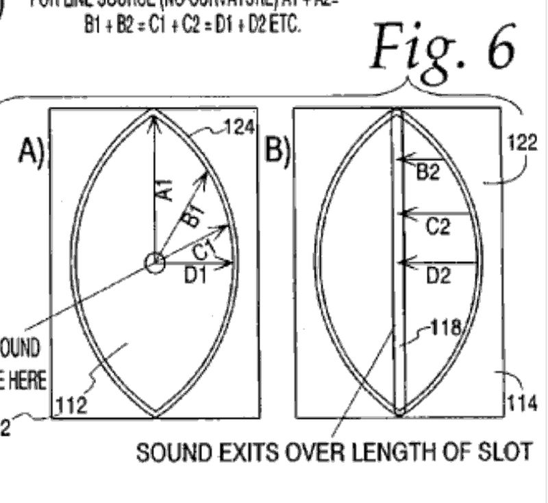
So far as the Paraline as used in the VTC array and GH-60, this is an acoustic device which can be shaped to provide an exit wavefront that can be flat, a line source or diverge or converge, an astigmatic point source with positive or negative focal point..
It works by allowing the sound to expand radially between two plate that are too close together to support any reflected modes between them so only radial expansion takes place.
It probably sounds weird to suggest that you can bend sound without ill effect but you can when the acoustic dimensions are small enough. The difference as it is in the examples above is that keeping the difference in path lengths less than about 1/4 wl at the highest frequency of interest.
"rho = density of air
c = speed of sound
d = diameter
Upper limit = 1,22 * c / d
lower imit = c / 4 / length of tube
... A plane wave tube is a tube the same size as the exit of the driver (or smaller or larger and including an adaptor to have a smooth transition from the driver's throat to the size of the tube). There is absorbing material in the tube which is designed to provide a certain load to the driver .... This load is supposed to be constant at all frequencies and allow easy comparison of different drivers, but in reality the size of the tube determines the frequency range measurements are useful in. The upper limit of the tube is set by the diameter. 1.22 * c / d is usually given as the upper limit. There will typically be a notch at this frequency and other notches above it. The lower limit is c / 4 / length of the tube."
Patrick - Thanks. I'd seen these and understand where you're coming from. I think all Tom Danley was saying in the first quote was that you don't get modes forming as between the plates, not that you don't get a wave forming along the direction of travel. The second post about plane wave tubes also confirms this - take a tube of about 2.5cm diameter and 2m long, and you'll be able to measure the soundwaves inside the tube between c.43hz and 16.7khz. Reduce the diameter to 2cm and you can measure higher to 20.9khz.
JLH - thanks for the Hornresp illustration. I didn't realise that you could use Hornresp like that. Is the way to calculate what size of bend will impact the wave simply to look at the path length difference between the 'inside' and 'outside' edges and make sure that the difference is less than c.1/4 of the wavelength of the highest frequency you want to pass unaffected? It seems to be from Tom Danley's post quoted by Patrick. (Maybe this is all there is to it in practice, even if the maths/physics is actually more complex. My father was a fluids engineer and one of the few work'related things I remember him saying was that he avoided right-angle bends as much as possible when designing fluid systems because of the abrupt pressure change and turbulence it introduced to the flow of the liquids. I'm likely wrong to apply this by analogy here, and probably mis-remembering what he told me anyway.)
I decided to simulate the effect the passageway's acoustical size has on the wave propagation inside a paraline. I used Horn Response's wave front simulator. I modeled with two different frequencies (1KHz and 10KHz) and with, and without reflectors.
First picture is the paraline with reflectors. I removed the reflectors for the other set of simulations.
An externally hosted image should be here but it was not working when we last tested it.
The next pic is of a 1KHz frequency being played in the paraline with reflectors. As you'll notice the wave front flows around the bend without issue. It does this because the bend's acoustical dimensions are too small to have an effect.
An externally hosted image should be here but it was not working when we last tested it.
The next pic is the paraline without reflectors. Once again, due to the wave front being acoustically large, the bends are still invisible to it and have no impact.
An externally hosted image should be here but it was not working when we last tested it.
Now we bump up the frequency to 10KHz. We now start to see what happens when our wavelengths become short enough to "see" the acoustic image of the bends.
This next pic is the paraline with reflectors and a 10KHz signal being played. Look at how messed up the waves are. The size of this paraline is too large to support 10KHz. There is a lot of wave front discontinuity going on. However, we still get waves coming out of the mouth slot.
An externally hosted image should be here but it was not working when we last tested it.
Lastly, we have a paraline without reflectors playing a 10KHz signal. There is a lot of discontinuity just like the one with reflectors, however there is almost no output at the mouth slot. There is so much cancellation going on there is almost no waves making out the mouth slot.
An externally hosted image should be here but it was not working when we last tested it.
So, what does this tell us?
1.) If the passageways are sized to the correct dimensions for the highest frequency of interest, then there will not be problems with the bends.
2.) If you over size the passageway, you will get cancellations even with reflectors.
3.) At higher frequencies, having reflectors is better than not having them. I believe this is why you see Danley's paraline with reflectors.
Thanks, this is a useful analysis- it doesn't agree with my position but I am not always correct, I'll assume this model to hold.
Are the gaps 1/4" in this case?
The 10kHz is sufficiently problematic to say to me that I'd not want to use the paraline folding at that frequency, maybe 1-5kHz is a more reasonable operating band... but then, what do you do to get a matching treble wavefront?
Challenging indeed!
More than likely, I'll use one of these for my car. I'm going back and forth between the idea of puting one in the kicks, or under the dash.
The pic above gives you an idea of what an underdash unit would look like. On the left is a three-way horn with a Paraline. On the right is the footprint of an Image Dynamics CD1-PRO, for comparison's sake. My horn design has the following:
1 x Celestion CDX1-1425 and 4 x Goldwood GT-25, all loaded into a Paraline with a quarter wave frequency of 900hz
2 x Pyle 5" sealed back midranges, crossed over at 900hz-ish
It's basically the same design as what Yorkville and VTC are doing, but flipped on it's side. A unity Paraline allows us to get the midranges and the compression driver close enough together that we don't have to use digital delay, like VTC and Yorkville do.
At these dimensions the sheer size of the driver itself starts to be a problem; if that's the case I might see if there's something that's much shallower that would do the job.
Patrick - thanks. I don't think it will necessarily fit in your space, but I've been thinking about combining three eye paralines, on the end of a conical horn. The centre paraline would be the HF compression driver. And then immediately to either side of the slot centre exit would be the slot exits for the mid drivers. However, the latter exits would not be in the middle of their respective eyes but at one edge. That way I can put the exits all pretty close together - by reversing the mid-eye paralines and having them face the HF paraline with the exits at the throat of the subsequent horn, or by having the faces of the mid-paralines form the walls of the subsequent horn. The pathlengths of all three would be the same (more or less), although the widths of the slots, etc. will differ to account for the different frequency ranges. The difficulty that I'm still thinking through is that to keep the pathlengths as between the HF and mid drivers similar, I have to accept that I end up with slightly different horn profiles as between the HF and mid drivers (the fomer being in effect a single conical throughout and the latter a two stage conical). My basic and probably inept modelling in Hornresp says that this should be OK.
Thanks, this is a useful analysis- it doesn't agree with my position but I am not always correct, I'll assume this model to hold.
Are the gaps 1/4" in this case?
The 10kHz is sufficiently problematic to say to me that I'd not want to use the paraline folding at that frequency, maybe 1-5kHz is a more reasonable operating band... but then, what do you do to get a matching treble wavefront?
Challenging indeed!
The gap in this model was 1" inch. Thus the reason why 10KHz falls apart. Based on the paraline patent 4500Hz would be the highest you want going through this model.
If the dimensions are sized correctly, any and do mean ANY frequency can be passed along in the paraline without issues. You just have to size it for the highest frequency of interest. Its all just a matter of scaling. It really is that simple.
JLH - thanks for the Hornresp illustration. I didn't realise that you could use Hornresp like that. Is the way to calculate what size of bend will impact the wave simply to look at the path length difference between the 'inside' and 'outside' edges and make sure that the difference is less than c.1/4 of the wavelength of the highest frequency you want to pass unaffected? It seems to be from Tom Danley's post quoted by Patrick. (Maybe this is all there is to it in practice, even if the maths/physics is actually more complex. My father was a fluids engineer and one of the few work'related things I remember him saying was that he avoided right-angle bends as much as possible when designing fluid systems because of the abrupt pressure change and turbulence it introduced to the flow of the liquids. I'm likely wrong to apply this by analogy here, and probably mis-remembering what he told me anyway.)
1/3 wavelength of the highest frequency appears to be the number in the paraline patent. It also happens to be very convenient that 1/4" works out to being 1/3 a wavelength at 18KHz. Lots of choices for 1/4" thick material.
You can only use some of the principles of fluid dynamics with sound. What your father would be concerned with is continuous flow in a pipe. With sound we are dealing with an AC signal that reciprocates back and forth. Not everything applies.
Below are more simulations. This time I the sized the gaps at 1/4" and 4.5" respectively.
Notice how the 10HKz wave is fully intact and doesn't have any issues.
The next pic is a paraline with a 4.5" gap height. Notice how it can't even handle 1KHz without lots of cancellation.
So to restate the obvious. As long as you size the gap height in the paraline for the highest frequency you want to play thought it, there will not be any issues.
Notice how the 10HKz wave is fully intact and doesn't have any issues.
An externally hosted image should be here but it was not working when we last tested it.
The next pic is a paraline with a 4.5" gap height. Notice how it can't even handle 1KHz without lots of cancellation.
An externally hosted image should be here but it was not working when we last tested it.
So to restate the obvious. As long as you size the gap height in the paraline for the highest frequency you want to play thought it, there will not be any issues.
Sorry if the following is idiotic, but I was thinking about the comment made where the timing of the wavefront thru the paraline could be altered (one end compared to another) to create a "lobe" (I have no other word) in the response to throw sound downward from a ceiling level sound system.
Could the same technique be used to offset a few inches of PL differential in the car audio environment?!?! Maybe the output of the paraline could be physically guided so the near side listener would receive the sound a few milliseconds later (longer pathlength inside the paraline) to create a physical time alignment?!?!?
Also, I am starting to envision a paraline-like device that has multiple folds on one end transitioning to a single fold on the other...short PL on one end, longer in the middle, & looong on the opposite end.
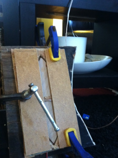
I whipped up a crude cross section...hope it can be understood. Basically the long PL end of the device has deep "folds", the middle has more shallow folds (not easily visualized from this drawing), and the short PL end has faded to no depth in the extra folds. This adds to the device depth of course.
Could this give us a few inches of "time delay" to the near side listener to offset the inherent PL differential in the car?!?!?
Could this give us a few inches of "time delay" to the near side listener to offset the inherent PL differential in the car?!?!?
An externally hosted image should be here but it was not working when we last tested it.
Sorry if the following is idiotic, but I was thinking about the comment made where the timing of the wavefront thru the paraline could be altered (one end compared to another) to create a "lobe" (I have no other word) in the response to throw sound downward from a ceiling level sound system.
Could the same technique be used to offset a few inches of PL differential in the car audio environment?!?! Maybe the output of the paraline could be physically guided so the near side listener would receive the sound a few milliseconds later (longer pathlength inside the paraline) to create a physical time alignment?!?!?
Also, I am starting to envision a paraline-like device that has multiple folds on one end transitioning to a single fold on the other...short PL on one end, longer in the middle, & looong on the opposite end.
Yep you can.
Crazy huh?
Even crazier, you can have the delay vary by angle.
So, for instance, you could do the following:
- Put the Paraline on it's side
- Put it directly in front of you. In this configuration, we would expect the soundstage to be parked right in front of us, due to the speaker being in front of us
- But it's possible to have the delay vary by angle. For example, you could have a large delay on axis, and a smaller delay off axis. This would 'drag' the image to the right, or at least it would below 1khz or so. (our perception of soundstaging is frequency dependent; at low frequencies we're sensitive to phase, so delay is effective. At high frequencies, not so much.)
You can also vary amplitude by angle.
There's definitely some uses for this thing as a soundbar under a TV set
I whipped up a crude cross section...hope it can be understood. Basically the long PL end of the device has deep "folds", the middle has more shallow folds (not easily visualized from this drawing), and the short PL end has faded to no depth in the extra folds. This adds to the device depth of course.
Could this give us a few inches of "time delay" to the near side listener to offset the inherent PL differential in the car?!?!?
An externally hosted image should be here but it was not working when we last tested it.
I'll have to think about the pic above before I can comment on it.
I *do* know that you can do a 'delay by angle' like this:

Picture the Paraline as a disc. The sound expands radially, in a series of concentric circles.
If you increase the distance from the center, you've inserted a delay. Obviously this is fairly subtle; an addition of 3.4cm is equivalent to one tenth of a millisecond.
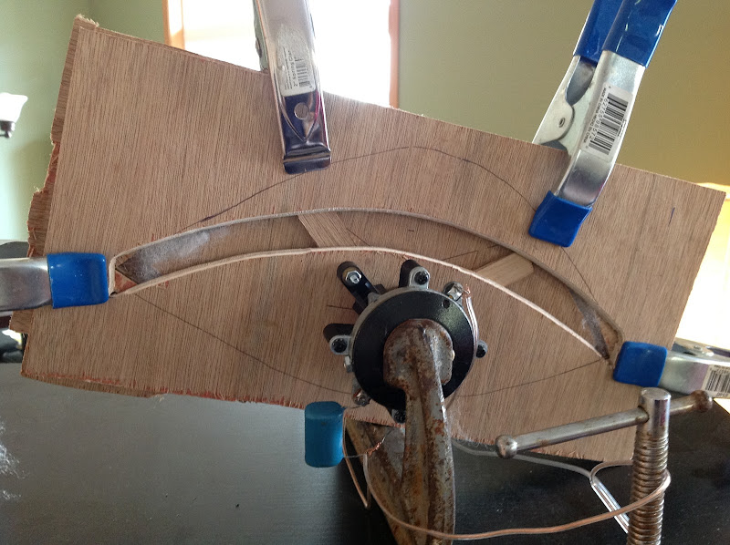
And since the disc is folded inside of the Paraline, you can vary the delay by angle by making the disc elliptical or egg shaped.
I've tweaked the drawing with a section depicting the familiar "eye" shape to help visualize what I am talking about.
An externally hosted image should be here but it was not working when we last tested it.
That's an interesting way to look at it- an "eye" shape could be used to enhance vertical directivity even in a simple round horn. While the horn shape naturally would allow closer C2C spacing, you could introduce some directivity while still having the horn load down to the frequency allowed by the larger vertical mouth dimension.
Pretty slick. Now, if I can just find the piece for the "throat" for screw-on horns. The female 1 3/8" 18TPI isn't a problem, but the male, with a reasonably shaped throat, could be.
JLH, can I ask you to run your sim with varying apeture size? It'd be interesting to see.
Pretty slick. Now, if I can just find the piece for the "throat" for screw-on horns. The female 1 3/8" 18TPI isn't a problem, but the male, with a reasonably shaped throat, could be.
JLH, can I ask you to run your sim with varying apeture size? It'd be interesting to see.
That's an interesting way to look at it- an "eye" shape could be used to enhance vertical directivity even in a simple round horn. While the horn shape naturally would allow closer C2C spacing, you could introduce some directivity while still having the horn load down to the frequency allowed by the larger vertical mouth dimension.
Pretty slick. Now, if I can just find the piece for the "throat" for screw-on horns. The female 1 3/8" 18TPI isn't a problem, but the male, with a reasonably shaped throat, could be.
JLH, can I ask you to run your sim with varying apeture size? It'd be interesting to see.
If I'm not mistaken, JLH is doing the sims by drawing the shape by hand. (You can 'sketch' any shape you want using your mouse. You can add and delete walls at will.)
To get the dimensions correct, start out with a plain' ol U-Frame and go from there.
If I'm not mistaken, JLH is doing the sims by drawing the shape by hand. (You can 'sketch' any shape you want using your mouse. You can add and delete walls at will.)
To get the dimensions correct, start out with a plain' ol U-Frame and go from there.
You are correct sir.
- Home
- Loudspeakers
- Multi-Way
- Square Pegs