You guys have way too much fun.
This seems to be an exciting next project that is quick and easy. Can't wait to start...
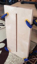
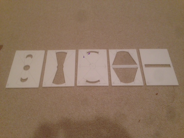
To be perfectly clear, what we built was a 2 ft x 1 ft tall "conventional" paraline , out of scraps of 1/4" MDF and ply I had lying around in my garage. The compression driver was my single eminence PSD2002 screw-on driver mounted into a piece of 3/4" MDF that was attached to the 1st paraline plate.
Despite out best efforts to mess it up, it sounds decent down to maybe 1 KHz . The paraline seems to have taken the harsh edge off the PSD driver,for better or worse and has spectacular constant directivity , even without a horn extension tacked on it.
Rigging up a "very makeshift" horn significantly improved the SPL .
If I were to build another one, I would
* first align all the pieces via some guide holes
* cut out the center piece first
* Use that as a template with a plunge router to derive the other pieces as necessary with the jigsaw being used only as a last resort
Attachments
Last edited:
You guys have way too much fun.
This seems to be an exciting next project that is quick and easy. Can't wait to start...
X, I wait with baited breath!
")
Ken, I'd love to hear your drunken tall Paraline! Do you have any audio or YouTube videos of it?
I was shooting for 3fe22 by
itself, maybe close to full range with no synergy xover if the Faital can handle it.
This sounds like a really good idea!
I started to layout a design for this with a 6 in tall exit slot and a 9in wide (4.5in half width for flow to fold 180 deg). The exit slot is 20mm wide and the inlet is a 1.0 dia for a CD. The material is 0.1875in thick. The expansion goes linearly from 1in to 6in with a mid injection at 3.0 in from CD inlet centerline.
I decided to model it in Akabak first to see if I can optimize the geometry in terms of location of injection point, dia of injection hole, width of exit slot, etc. This is with a flat exit plane (no external round cylinder horn).
Here are the results of the model assuming a 6in Eminence Alpha sealed back mid 6CBMRA x qnty 2 and a B&C DE250 CD.
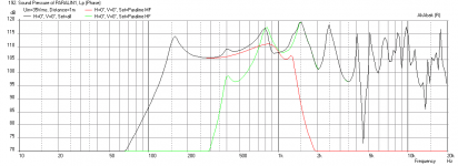
With a XO freq of 700Hz here is what I get for frequency response at 2.83V:

Kind of ugly...
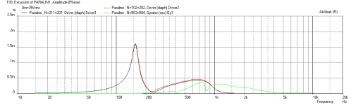
Cone excursion at 35v for 1.5mm xmax:
SPL at xmax:
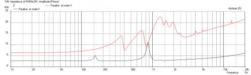
Impedance:
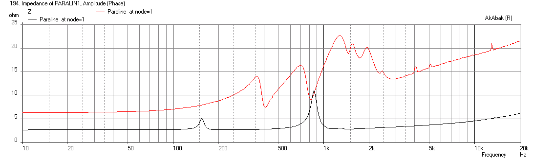
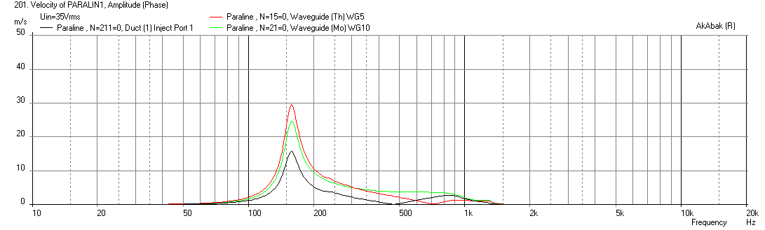
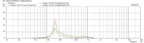
Velocities in channels and at exit slot (that's cooking through there):
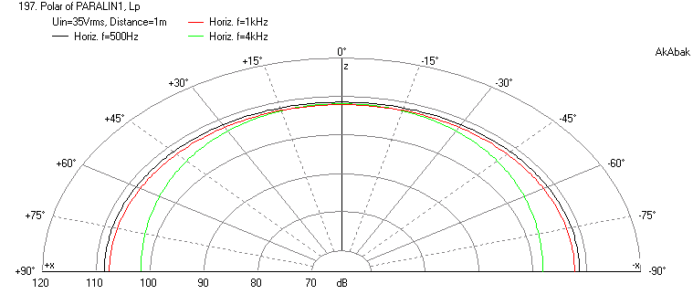
Horizontal Polar - very nice:
Given how ugly this looks, I will only try it because foam core is so easy to make. I am not expecting good results though...
Attachments
And here's another lame idea:
See that thar Smithagrain thingie a few posts back...
Just now occurs to me, we could hang that in a corner
and blend 90 degree directivity into 90 degree walls
with barely any glitch at the wall interface and almost
no concern for how the rest of the horn fits behind it.
If really lazy (and I *know* I am) or wanting to travel:
You could just lean it into some random corner on a pole.
Where as long as the pole didn't slip or get tripped over,
it would probably stay put just fine. No hanging required.
Re: XRK
180?!? You are plotting vertical polars without a roundover, because horizontal is 90
set by the internally folded waveguide. Akabak could not possibly have simulated the
time and distance smear of reflections and transitions set at deliberate internal angles
to avoid typical paraline-like rough response.
I'm still not at sure from your last response that you understand the slot is horizontal?
6 inches tall makes absolutely no sense in this context. Its also less mouth area than
the surface area of your mids. So unless this is the throat of something greater, i am
extremely misunderstanding your intentions.
Also your comments in #738 seem to indicate that you expect every path should be
made equidistant to the exit, which is definitely not what was intended here at all...
This shapes a 90 degree curved wavefront, not a line array. If you are trying to build
a proper paraline with a vertical slot, please do not follow my drawing, it will not get
you there.
Last edited:
I do have it aligned vertically, but even in the other directions, the result of the polar is almost the same and it has to do with fact that the model is basing the polar on the thin slit like radiator element. I am not sure the sharp bends would have anything to change the polars as it is appearing close to a point (or line source). Once I add the external horn it will be different. I did not realize you intended it to be used horizontally, and now that you say it is a smith horn that sort of makes sense. I actually made my design different from yours in that the curved slots are bent the other way more like a paraline parabola, but the arc is cut off and not the full 180 deg. The skeleton of the model is now in place and I can play with the particulars of the geometry later.
I have actually already started looking at the 3FE22/25 with larger rear chamber than a sealed back mid which tends to have a peak at 150Hz. I don't know how real that 5kHz dip is - playing with geometry of folded Paraline to see if there is any effect. Good news is that the 3FE25 looks very nice - cheaper than a sealed pro mid driver and smoother performance. I am also adding a radial front horn kind of smith horn like and it really improves system sensitivity up to 105dB at 1m and 2.83v. I will post new sims as soon as I can put it all together in a coherent story.
Those findings are pretty encouraging from my humble standpoint!
One thing I wasn't too sure on was the intended range/bandwidth you were considering for those drivers. Are you going to run them across their entire frequency, or have them function more like mids, combining them with a separate HF driver?
One thing I wasn't too sure on was the intended range/bandwidth you were considering for those drivers. Are you going to run them across their entire frequency, or have them function more like mids, combining them with a separate HF driver?
I do have it aligned vertically, but even in the other directions, the result of the polar is almost the same and it has to do with fact that the model is basing the polar on the thin slit like radiator element. I am not sure the sharp bends would have anything to change the polars as it is appearing close to a point (or line source). Once I add the external horn it will be different. I did not realize you intended it to be used horizontally, and now that you say it is a smith horn that sort of makes sense. I actually made my design different from yours in that the curved slots are bent the other way more like a paraline parabola, but the arc is cut off and not the full 180 deg. The skeleton of the model is now in place and I can play with the particulars of the geometry later.
Based on a slot nearly 2 feet wide, the polar is not 180, but that of the
folded horn behind it. If you have curved like paraline, directivity will be
ridiculously narrow. Appearing to emanate from an infinitely deep and
narrow horn. Though the true throat is much closer, at parabolic focus.
The horn appear longer than it is.
In the cassegrain case, the internally folded horn is 90 degrees, and the
throat appears to be at the apex of the 90 deg triangle. Though the true
throat is actually further back at the apex of the 45 degree triangle. I did
that so we could have exponential expansion without exponential directivity.
The horn appears shorter than it is.
External horn will mostly affect how the slot radiates from its thin 2cm
tall dimension. 2cm is slightly too wide for full range 180deg, and will
beam if you plot the polars above 4K. But considering this is vertical
directivity, and additional narrowing by external horn, that feature of
a slightly wider than ideal horizontal slot isn't necessarily problematic.
I can't imagine any benefit to make internals narrower than 5mm.
Anything up to 1cm should work, excepting that 1cm makes for a 2cm
slot where a pair meet at the exit. So 5mm is widest that works without
beaming in all cases. You are 4.76mm which is fine, but calls for 9.92mm
exit slot, not 20mm. That mismatch may beam slightly for no meaningful
reduction in velocity. I would just widen the internals and bring the wind
speed down, as I'm OK with a little vertical beaming.
Again, neither directivity is 180. You are over-trusting a meaningless sim.
Last edited:
Again, neither directivity is 180. You are over-trusting a meaningless sim.
IAWTC
The Paraline is simply a radial horn that's been folded.
You can sim it as a radial horn.
In the real world, you'll find that the fold does two things:
1) it adds some peaks and dips to the response, likely due to the fact that a fraction of the output is reflected by the 180 degree bend. (Higher Order Modes)
2) In my experiments, the high frequencies are rolled off more dramatically than in a conventional waveguide. IE, if you could generate 90dB at 15khz with a compression driver on a conventional waveguide, you'd be lucky to get 80-85dB on a Paraline.
To my ears, the Sausalito Audio Works Lens serves a similar function but sounds more 'delicate.' It's like comparing a ribbon to a dome. Both devices are tweeters but one sounds 'airier."
If I was going to cut off any part of the internal arc of a paraline, it would be the middle.
The ends are where the distance to reflection smear is best. You could interleave two
such centerless paralines (or half paralines) and still present a continuous line of exits.
The Smith case is even better, as not only the internal reflection time, but also exit time
is well smeared. Though Smith doesn't array well vertically, for smear it wouldn't need to.
And you can array them horizontally, even omni. Even seamless with their own reflection
if angled properly against a wall or corner.
Danley's tall multi-off-center-paralines array has a lot of smear factor going for it too.
I would not expect the cumulative response to be ragged. But smooth to an average.
And we have yet to throw foam at our problems, which is silly, because filter sheets are
so readily available and easily trimmed to complex but flat internal shapes.
Last edited:
Based on a slot nearly 2 feet wide, the polar is not 180, but that of the
folded horn behind it. If you have curved like paraline, directivity will be
ridiculously narrow. Appearing to emanate from an infinitely deep and
narrow horn. Though the true throat is much closer, at parabolic focus.
The horn appear longer than it is.
In the cassegrain case, the internally folded horn is 90 degrees, and the
throat appears to be at the apex of the 90 deg triangle. Though the true
throat is actually further back at the apex of the 45 degree triangle. I did
that so we could have exponential expansion without exponential directivity.
The horn appears shorter than it is.
External horn will mostly affect how the slot radiates from its thin 2cm
tall dimension. 2cm is slightly too wide for full range 180deg, and will
beam if you plot the polars above 4K. But considering this is vertical
directivity, and additional narrowing by external horn, that feature of
a slightly wider than ideal horizontal slot isn't necessarily problematic.
I can't imagine any benefit to make internals narrower than 5mm.
Anything up to 1cm should work, excepting that 1cm makes for a 2cm
slot where a pair meet at the exit. So 5mm is widest that works without
beaming in all cases. You are 4.76mm which is fine, but calls for 9.92mm
exit slot, not 20mm. That mismatch may beam slightly for no meaningful
reduction in velocity. I would just widen the internals and bring the wind
speed down, as I'm OK with a little vertical beaming.
Again, neither directivity is 180. You are over-trusting a meaningless sim.
How can using 1 cm panels work? That would correspond to a 1/4 frequency of 8.5 KHz
Paraline is a 360 radial horn, then a plane wave, then a 180 (or less) radial horn.
Hard impedance changes occur at regular intervals.
Smithagrain is a 90 degree radial horn (pair of 45's), then a 180 degree radial horn
(pair of 90's), then a huge vertical roundover that boosts treble on vertical axis.
Softer impedance changes occur at smeared intervals.
Wide horizontal directivity attenuates treble for both is to be expected.
I don't image they would misbehave the same internally in terms of ragged.
Until a smithagarin has been correctly built and measured, can't say for sure.
I should probably use same compression driver and slot for comparing apples...
Last edited:
How can using 1 cm panels work? That would correspond to a 1/4 frequency of 8.5 KHz
Oh crap, you might be right... 4.25mm at 20KHz. I will update the drawing.
Here's a low resolution measurement of one of my Paralines. Sorry about the crummy measurement, my PC wasn't working when I built it:
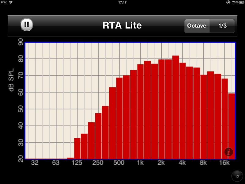
This one is a Synergy horn, which is why it goes down to 500hz
Here's a measurement of the on-axis and 180 degrees off axis of a SAW lens. See how the off axis 'tracks' the on-axis closely, it's just lower in level? (Which is what we want.)
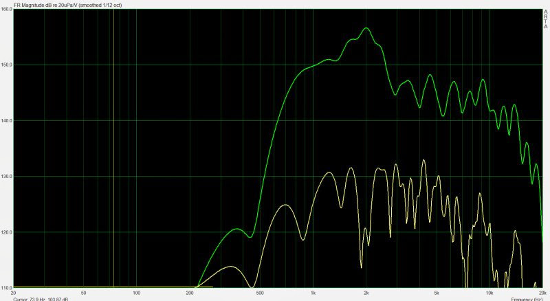
More info here: http://www.diyaudio.com/forums/multi-way/239808-28-days-later-3.html#post3587195
This one is a Synergy horn, which is why it goes down to 500hz
Here's a measurement of the on-axis and 180 degrees off axis of a SAW lens. See how the off axis 'tracks' the on-axis closely, it's just lower in level? (Which is what we want.)
More info here: http://www.diyaudio.com/forums/multi-way/239808-28-days-later-3.html#post3587195
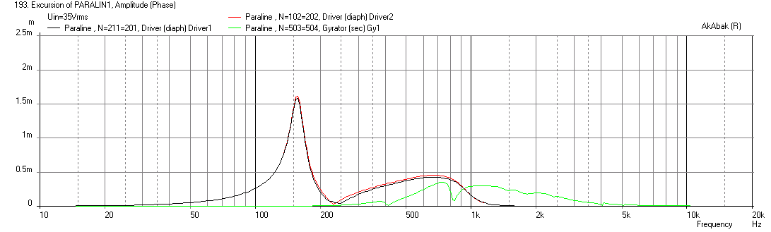
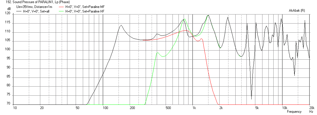
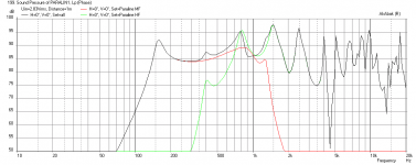
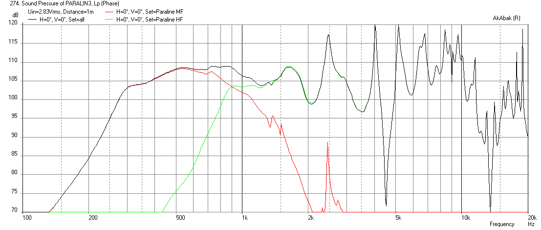
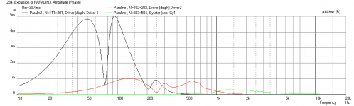
Paraline with 2x 3FE25 MF and DE250 HF
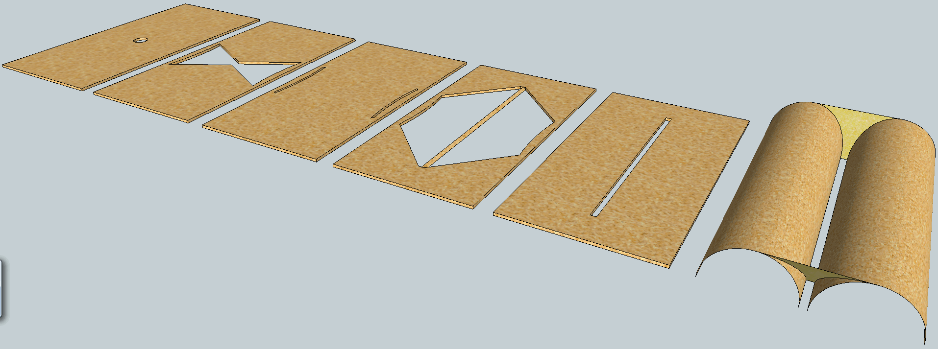
Here is a sim of my paraline with the geometry shown in the photo below. The panels are 10in wide x 7in tall with the exit slit 6in tall x 20mm wide. The foam core is 0.1875in thick. The crescent shaped holes are for the MF drivers. The sim also includes a 21.5in wide x 10in tall x 20in deep radial horn to bring the sensitivity up. A 1200Hz -24dB/oct XO is used here.
Freq response:
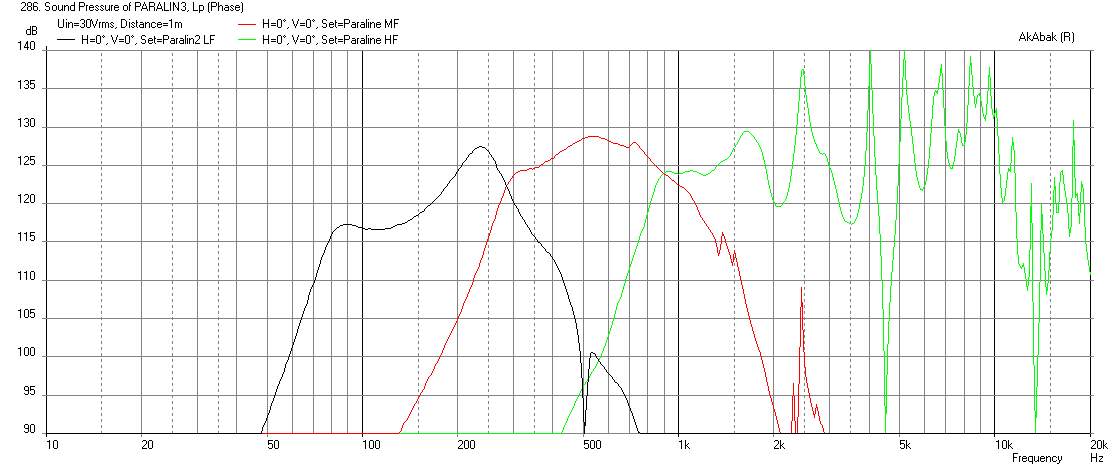
If I add qnty 4 x Tang Band W5-876SE woofers to the outer radial horn with qnty 4 x 3in dia x 11in long BR ports we get this at a driver voltage of 30v to hit the xmax of the woofers at 5mm:
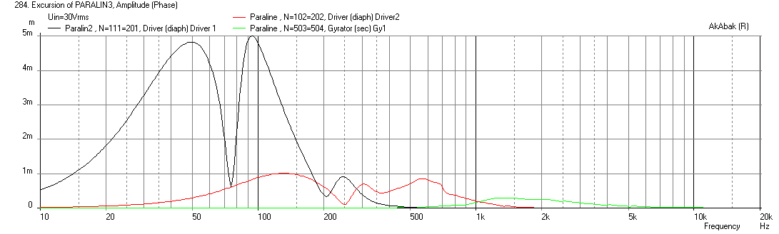
Here is the displacement for all 3 drivers (LF, MF, HF) at xmax:
As a three-way, it really should use some higher sensitivity drivers of maybe 100dB 12 inchers (8ohm) x qnty 2 in parallel for 106dB bass sensitivity.
Here is a sim of my paraline with the geometry shown in the photo below. The panels are 10in wide x 7in tall with the exit slit 6in tall x 20mm wide. The foam core is 0.1875in thick. The crescent shaped holes are for the MF drivers. The sim also includes a 21.5in wide x 10in tall x 20in deep radial horn to bring the sensitivity up. A 1200Hz -24dB/oct XO is used here.
Freq response:
If I add qnty 4 x Tang Band W5-876SE woofers to the outer radial horn with qnty 4 x 3in dia x 11in long BR ports we get this at a driver voltage of 30v to hit the xmax of the woofers at 5mm:
Here is the displacement for all 3 drivers (LF, MF, HF) at xmax:
As a three-way, it really should use some higher sensitivity drivers of maybe 100dB 12 inchers (8ohm) x qnty 2 in parallel for 106dB bass sensitivity.
Attachments


Last edited:
- Home
- Loudspeakers
- Multi-Way
- Square Pegs