I've read this entire thread, and can really appreciate the attention to detail that everyone has put in, in terms of calculations and testing.
I'd like to make some studio monitors. Would it be worth using a paraline for mid and high frequency output, and then a (sub) woofer of some kind for the low frequency range?
I know the theory has been discussed about using a large (height + width) paraline to get the full range, but I've not seen any implementations of that. That might not work in the room(s) that I have access to, so the mid-high paraline would be more suitable.
Would coupling it to a horn be necessary? I'm probably going to be sitting in a sweet spot, so going by Patrick's demonstration it doesn't seem to be the case.
The Paraline is not a good choice for studio monitors, even with a 90 degree waveguide, as the response is quite ragged.I've read this entire thread, and can really appreciate the attention to detail that everyone has put in, in terms of calculations and testing.
I'd like to make some studio monitors. Would it be worth using a paraline for mid and high frequency output, and then a (sub) woofer of some kind for the low frequency range?
Would coupling it to a horn be necessary?
Review posts #92,114,204,284,311, 314, 342.
The Paraline is not a good choice for studio monitors, even with a 90 degree waveguide, as the response is quite ragged.
Review posts #92,114,204,284,311, 314, 342.
JLH is using a Paraline for his Synergy Horn project;
would love to hear him chime in with why he went that route.
I find my Paralines to be very 'listenable', and the very narrow directivity has a way of making a bad room a non-issue.
But it's true, the measured response is ugly.
I have new ideas on where the frequency response issues are coming from. Danley has solved them, so I believe I can too. Quite frankly, as long as it has good fidelity I really don't care (within reason) what the frequency response looks like. See the updated Danely Paraline SBH-10 data sheet with frequency plot.
http://www.danleysoundlabs.com/danl.../10/SBH-10-Preliminary-Spec-sheet-updated.pdf
http://www.danleysoundlabs.com/danl.../10/SBH-10-Preliminary-Spec-sheet-updated.pdf
Normally we agree on most things, but I'm afraid there isn't much evidence that Danley has fixed the frequency response problem.
Here's possibly the best measurement of a DIY Paraline. This was done by Nate Hansen and uses a BMS:
In the response graph posted by Danley, the undulations in the frequency response are present. It measures +/- 4dB, about the same as Nate's. (Assuming Nate normalized his with EQ.)
Here's possibly the best measurement of a DIY Paraline. This was done by Nate Hansen and uses a BMS:
In the response graph posted by Danley, the undulations in the frequency response are present. It measures +/- 4dB, about the same as Nate's. (Assuming Nate normalized his with EQ.)
What's wrong with +/-4dB? Anybody that has listened to the video of the SBH-10 can't tell me it doesn't sound good. I've seen worse measuring speakers than the SBH-10 sound very good. The undulations don't bother me. Danley fixed the deep nulls like the ones that appear in Nate's graph around 2.5KHz. Nate's measurement is equalized.
Nothing wrong with +/- 4 dB.What's wrong with +/-4dB? Anybody that has listened to the video of the SBH-10 can't tell me it doesn't sound good. I've seen worse measuring speakers than the SBH-10 sound very good. The undulations don't bother me. Danley fixed the deep nulls like the ones that appear in Nate's graph around 2.5KHz. Nate's measurement is equalized.
Nate's equalized measurements cover about a 30 dB range from 1000 Hz to 20 kHz, about +/-15 dB, not the type of response I'd want in a reference monitor.
A video "sounding good" is not indicative of a smooth response curve, there is no reference to compare it to.
Multiple Paralines with different vertical height in a array like the SBH-10 will tend to smooth the response compared to a single, but the response still won't be as smooth as the individual drivers used in it are.
The SBH-10 lost 3 dB in sensitivity from the pevious preliminary specification, it is only 96 dB one watt one meter, I suspect that more passive EQ was needed to "kinda" fit in to the +/- 3 dB window.I have new ideas on where the frequency response issues are coming from. Danley has solved them, so I believe I can too.
Assuming the 90 dB sensitivity BMS 5C150 coax is used, the SBH-10 is now -3 dB less than what one would expect from a front loaded array of eight of those drivers .
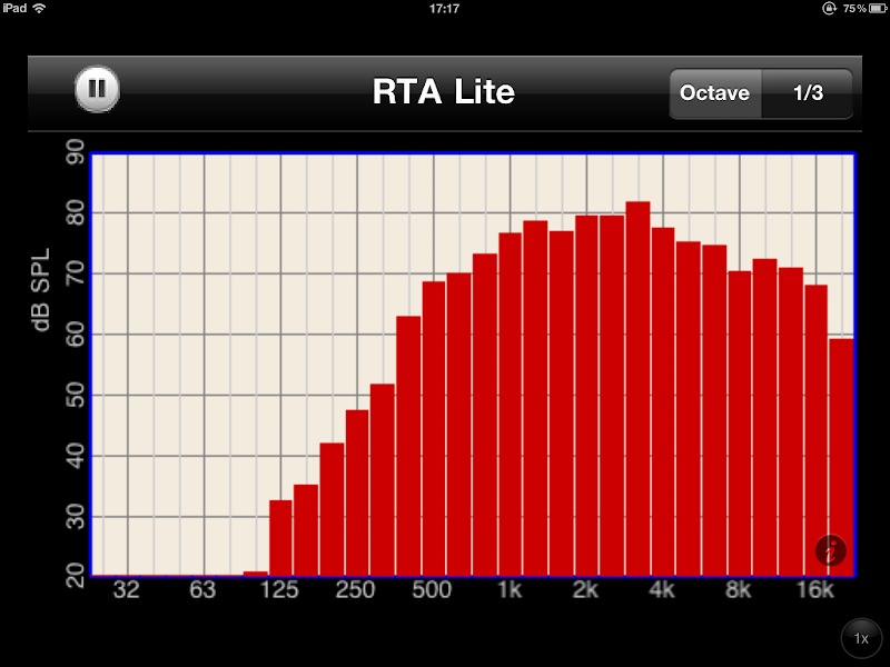
I recently redid the Dirty Dozen line array using 25 cent Jamo buyout speakers.
No crossover, just dirt cheap speakers wired in series parallel.
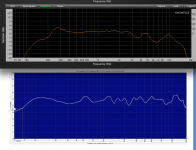
Though the response does not go as low or high, it is in general considerably smoother on axis than the SBH-10.
The charts below show the Dirty Dozen on above the SBH-10, the vertical scale is the same.
DSL has not "solved" the frequency response problems inherent in the Paraline, but has made them more tolerable.
Art
Attachments
Last edited:
I tried a bunch of byzantine folding schemes, in an attempt to make a Paraline that would fit under the dash of a car.
All kinds of bizarre stuff, such as varying the length on one side of the Paraline so that the compression driver can face *up* while the wave exiting it comes out to the *right*, and in phase. (Bending sound is easy, bending it and keeping it in phase is hard!)
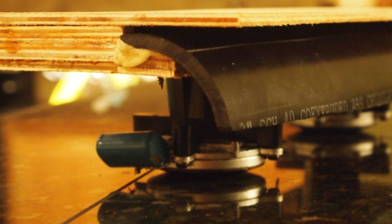
Frustrated by how hard it was, I simply cut a Paraline in half. That not only worked, it was actually smoother than a regular Paraline!
I'm not 100% certain WHY, but here's a few guesses:
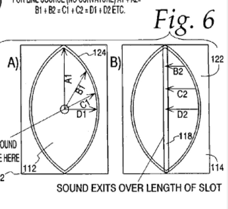
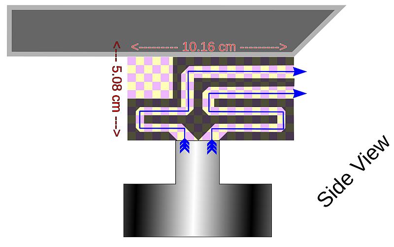
1) In a perfect Paraline, 100% of the sound would make it from the compression driver to the Paraline exit. But there isn't a perfect Paraline, and a fraction of that energy is reflected at various places in the Paraline. In the pic above, taken from the Paraline patent, it's safe to assume that a fraction of the sound will hit that eye shaped slot, and instead of going THROUGH the slot, it will get reflected back towards the throat. If the height of the Paraline is 18cm, about the size of the Paraline in the Danley SBH-10, that reflection will create a notch at 944hz. The tricky part is that the frequency of the notch isn't fixed; it changes with angle. So a notch is created at 944hz on the vertical axis, but on the horizontal axis the notch is at 1888hz, because the width of the Paraline is about twice as tall as it is wide.
At this point, ninety percent of you are scratching your heads, because that last paragraph is hideously confusing. Suffice it to say, the notches in the Paraline response are real, and they're frequency and angle dependent. It's quite a complex pattern, not easily fixed electronically.
But PHYSICALLY, there's a couple ways to improve things. First, fill the thing with foam a la Geddes. That will mop up some of the reflected energy, since the reflected wave goes through the foam more than the incident wave.
And a second way to physicaly improve the Paraline is to simply slice it in half. The reason that the response is smoother may be because the reflections off the near wall are very close in time. IE, in a Danley Paraline the reflection will occur between 944hz and 1888hz, due to geometry. In one of my 'half a Paraline' things, the reflection at 944hz and 1888hz will still happen, but only on one side while the reflection from the nearest wall will be at a much higher frequency (because the compression driver is flush with the wall.)
Another possibility is simply that my craftsmanship was better on this one, or that the roundover helped a lot.
Jury is still out, because I only built one.
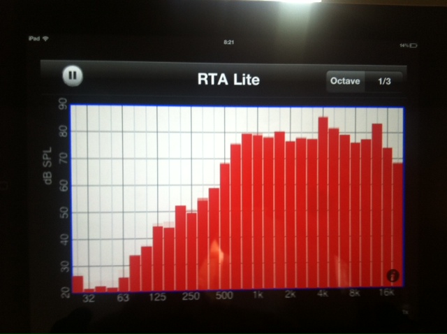
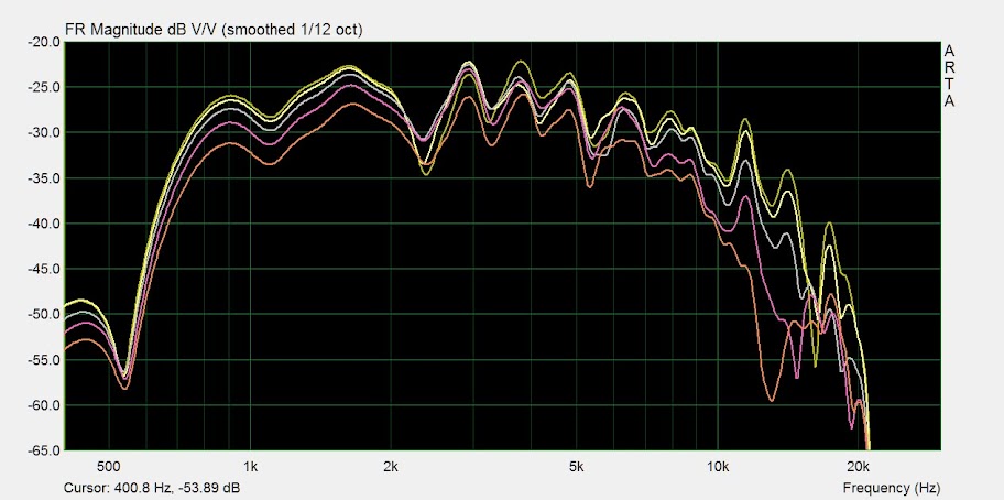
For comparison's sake, here's a measurement of one of my 'conventional' Paralines. See how my half-a-paraline thing is smoother?
All kinds of bizarre stuff, such as varying the length on one side of the Paraline so that the compression driver can face *up* while the wave exiting it comes out to the *right*, and in phase. (Bending sound is easy, bending it and keeping it in phase is hard!)
Frustrated by how hard it was, I simply cut a Paraline in half. That not only worked, it was actually smoother than a regular Paraline!
I'm not 100% certain WHY, but here's a few guesses:
1) In a perfect Paraline, 100% of the sound would make it from the compression driver to the Paraline exit. But there isn't a perfect Paraline, and a fraction of that energy is reflected at various places in the Paraline. In the pic above, taken from the Paraline patent, it's safe to assume that a fraction of the sound will hit that eye shaped slot, and instead of going THROUGH the slot, it will get reflected back towards the throat. If the height of the Paraline is 18cm, about the size of the Paraline in the Danley SBH-10, that reflection will create a notch at 944hz. The tricky part is that the frequency of the notch isn't fixed; it changes with angle. So a notch is created at 944hz on the vertical axis, but on the horizontal axis the notch is at 1888hz, because the width of the Paraline is about twice as tall as it is wide.
At this point, ninety percent of you are scratching your heads, because that last paragraph is hideously confusing. Suffice it to say, the notches in the Paraline response are real, and they're frequency and angle dependent. It's quite a complex pattern, not easily fixed electronically.
But PHYSICALLY, there's a couple ways to improve things. First, fill the thing with foam a la Geddes. That will mop up some of the reflected energy, since the reflected wave goes through the foam more than the incident wave.
And a second way to physicaly improve the Paraline is to simply slice it in half. The reason that the response is smoother may be because the reflections off the near wall are very close in time. IE, in a Danley Paraline the reflection will occur between 944hz and 1888hz, due to geometry. In one of my 'half a Paraline' things, the reflection at 944hz and 1888hz will still happen, but only on one side while the reflection from the nearest wall will be at a much higher frequency (because the compression driver is flush with the wall.)
Another possibility is simply that my craftsmanship was better on this one, or that the roundover helped a lot.
Jury is still out, because I only built one.
For comparison's sake, here's a measurement of one of my 'conventional' Paralines. See how my half-a-paraline thing is smoother?
Nothing wrong with +/- 4 dB.
Nate's equalized measurements cover about a 30 dB range from 1000 Hz to 20 kHz, about +/-15 dB, not the type of response I'd want in a reference monitor.
I wouldn't want +/-3 db in a reference monitor.
. Nate's measurement is equalized.
No eq there....... And I used 1/12 octave smoothing to pretty it up
 . I'm interested to see what you come up with JLH.
Like I said before they are fun to listen to, but I personally won't build any more Paralines for hifi.
No eq there....... And I used 1/12 octave smoothing to pretty it up
Like I said before they are fun to listen to, but I personally won't build any more Paralines for hifi.
That's what I thought (no EQ). Thanks for the confirmation. I'll share what find with my new ideas.
just by looking at it I can feel how genius the designer is..
An externally hosted image should be here but it was not working when we last tested it.
Looks like four 10 degree paralines combined in a horn to get 40 degrees of vertical coverage. The SPL output on that thing is probably obscene.
I wouldn´t mind trying a paraline synergy horn, and would be willing to do some 3d printing or CNC to get the parts right. I have been playing around with parabolics in CAD the last few days, so let me see if I get it right:
You can basically create any "shape" wavefront as you want (in one axis), and it doesn´t have to be symmetrical. If I understand you correctly (forgot which post you mentioned it in, so please correct me if I misinterpret) Patrick, any curved wavefront variant will be less plagued with resonances than one without.
So the idea is to be able to create a horn that is parallel to the floor on the bottom, and 30 degrees vertical directivity, combined with 60 degrees horizontal directivity. The reason is that the horn would be placed low, perhaps on top of a bass bin.
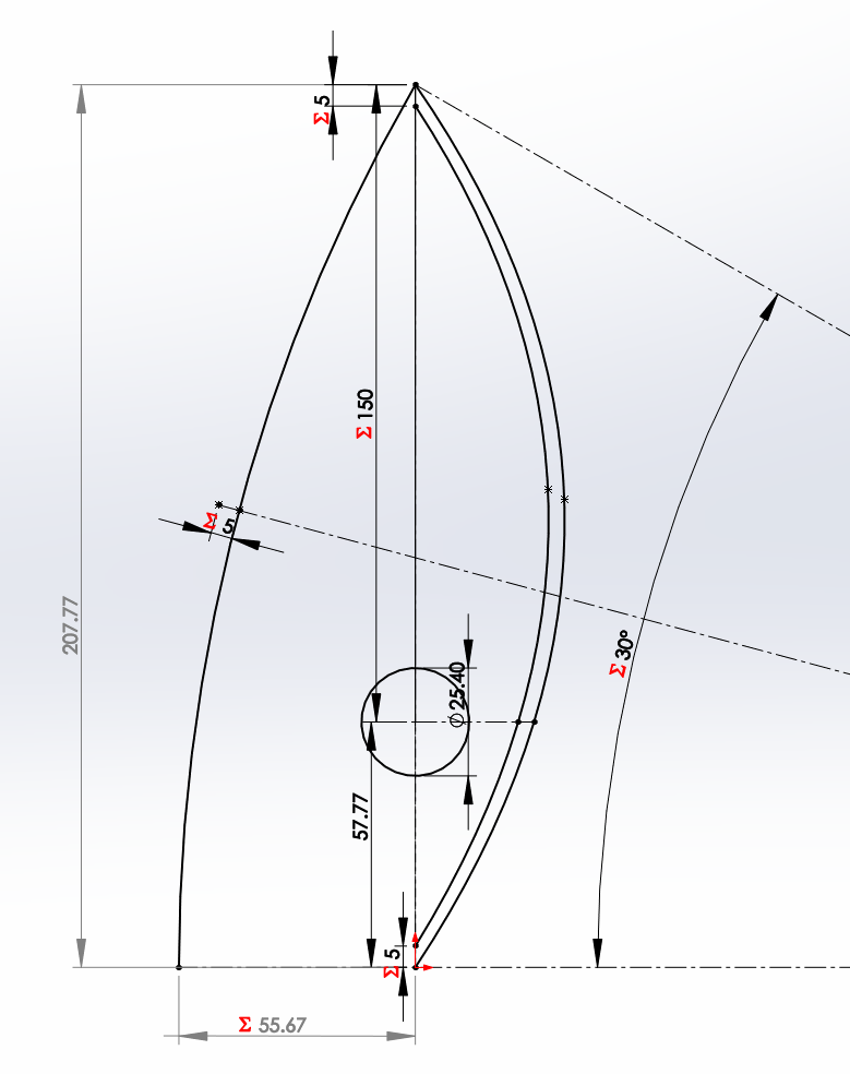
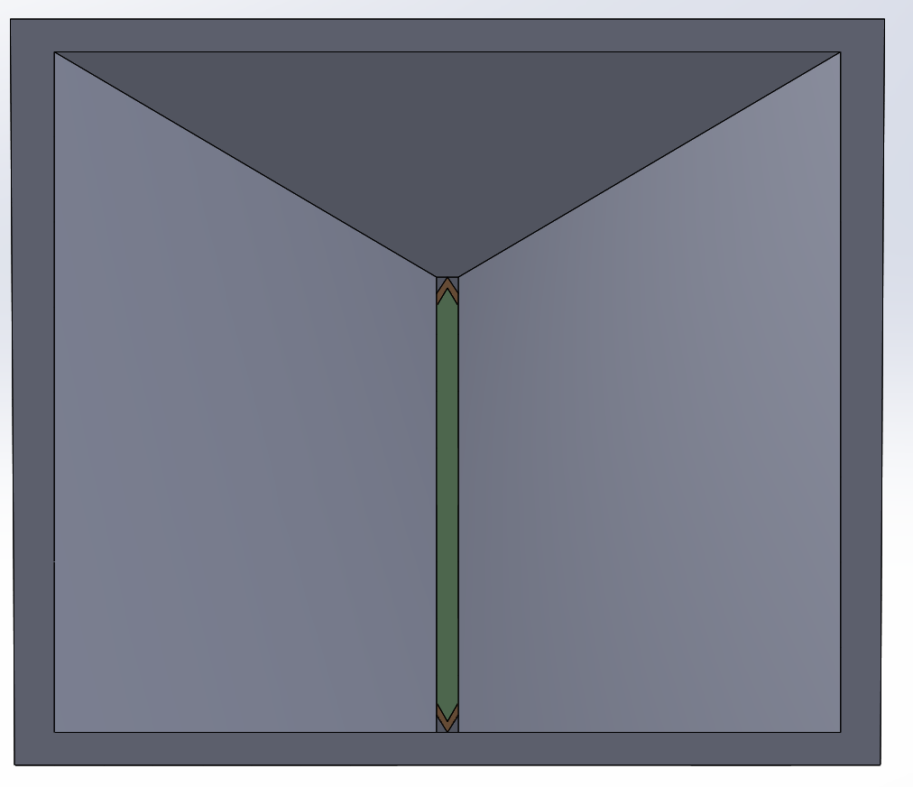
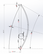
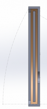
The shape I have used is like this, with somewhat arbitrary figures right now: 5 mm layer depth, 150mm path length to exit (to top of paraline), 30 degrees wavefront on the vertical axis.
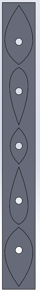
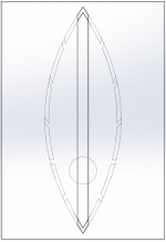
This turns into a paraline shaped like this:
The width of the exit slot is set to 2x layer depth.
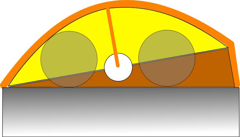
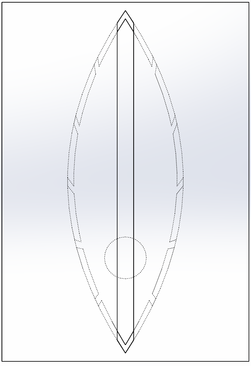
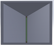
Seen from the side, this should give the a wave front like this:
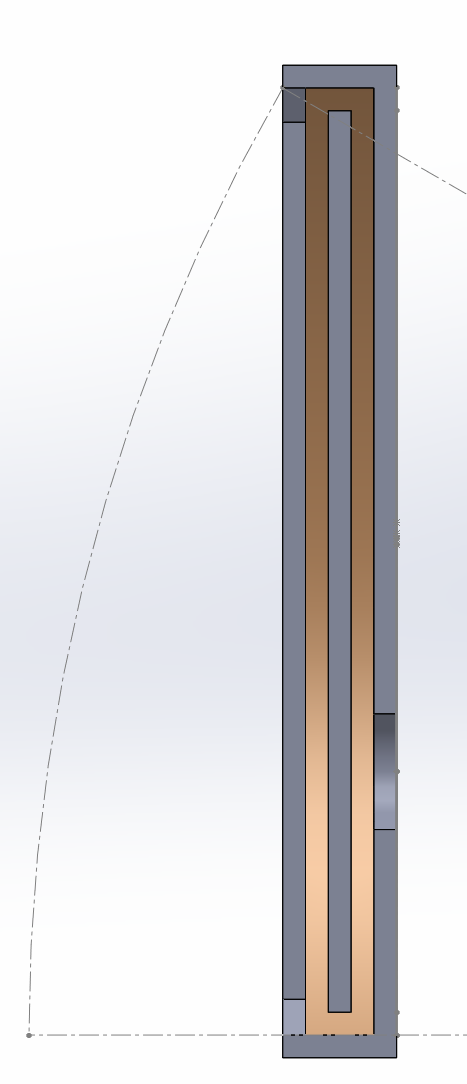
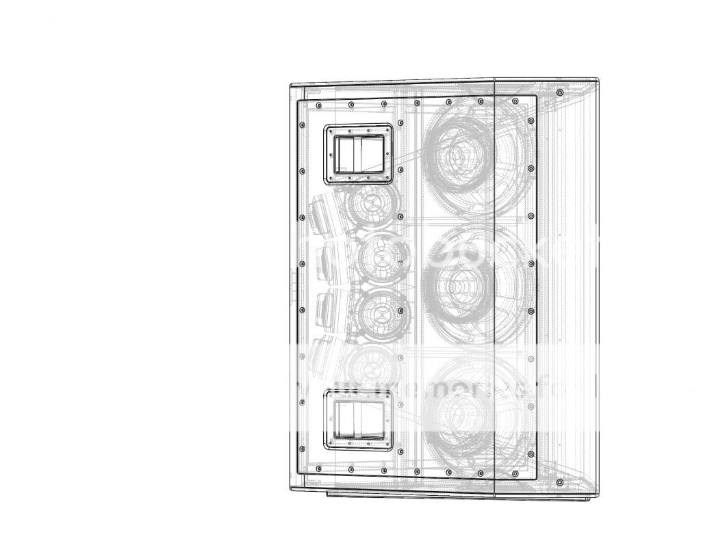
And such a horn shape should be possible:

And seen from the front:
I did not do any akabak simulations, calculate the required horn depth etc so far. What i´m looking for is for the experts in here to say whether or not I completely misunderstood the concept, and if not (i hope!) whether it´s worth building on.
If resonances (leading to jagged response) is a function of several equal distances, then this version should perhaps reduce that and spread resonances over a wider bandwidth. I didn´t fully build draw the paraline (missing reflectors etc) nor the horn (no anti-waistbanding flare), but wanted some feedback before continuing. Keeping everything parametric, so that it can easily be modified by changing values rather than redrawing everything.
In my post from december 12 I tried using the same principle to draw a line array with controlled vertical directivity, but realise now that the post was too brief to warrant any response..
Hope this post will be better received.
Note: it seems some images are squashed - they should be fine by clicking on them.
You can basically create any "shape" wavefront as you want (in one axis), and it doesn´t have to be symmetrical. If I understand you correctly (forgot which post you mentioned it in, so please correct me if I misinterpret) Patrick, any curved wavefront variant will be less plagued with resonances than one without.
So the idea is to be able to create a horn that is parallel to the floor on the bottom, and 30 degrees vertical directivity, combined with 60 degrees horizontal directivity. The reason is that the horn would be placed low, perhaps on top of a bass bin.
The shape I have used is like this, with somewhat arbitrary figures right now: 5 mm layer depth, 150mm path length to exit (to top of paraline), 30 degrees wavefront on the vertical axis.
This turns into a paraline shaped like this:
The width of the exit slot is set to 2x layer depth.
Seen from the side, this should give the a wave front like this:
And such a horn shape should be possible:
And seen from the front:
I did not do any akabak simulations, calculate the required horn depth etc so far. What i´m looking for is for the experts in here to say whether or not I completely misunderstood the concept, and if not (i hope!) whether it´s worth building on.
If resonances (leading to jagged response) is a function of several equal distances, then this version should perhaps reduce that and spread resonances over a wider bandwidth. I didn´t fully build draw the paraline (missing reflectors etc) nor the horn (no anti-waistbanding flare), but wanted some feedback before continuing. Keeping everything parametric, so that it can easily be modified by changing values rather than redrawing everything.
In my post from december 12 I tried using the same principle to draw a line array with controlled vertical directivity, but realise now that the post was too brief to warrant any response..
Hope this post will be better received.
Note: it seems some images are squashed - they should be fine by clicking on them.
Attachments

- Home
- Loudspeakers
- Multi-Way
- Square Pegs