Thanks! I had sort of started to visualize it by thinking of a fixed thickness bi-radial 180 deg horn ('thickness' being the 0.25" or whatever), and splitting it in half to form a circle and then folding it up, but your drawing is much better.
Once the shop gets fixed up, I may have to try building one.
JSS
Once the shop gets fixed up, I may have to try building one.
JSS
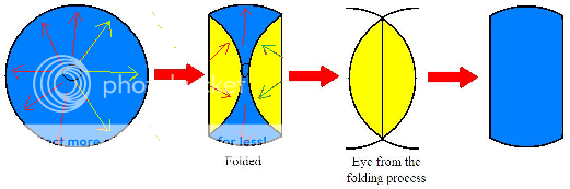
It’s always expanding. It is a circle that has two parallel sides folded over. There is no limit to how many times you fold up the sides of the circle. Instead of a single fold like in my attached picture, you can fold the sides into a Z shape.
I totally don't get that drawing. What's the last picture (rightmost). ?
As your measurement indicates, you made the mass rolloff even worse by placing a midrange onto the paraline. Being down 20dB with a dome tweeter is quite good. Even a compression driver is down a good 10dB most of the time.
The measurements were taken separately, tweeter only on the Paraline then mid in place of the tweeter. Hopefully I have time tonight to make up a quickie driver plate to mount 2 FR88's with closer to optimum ports on the Paraline with the dome tweet. I'm excited to hear it with proper crossovers and eq. Fun stuff for sure!
One qualifier statement that I think has to go along with the Paraline design is that it must be used with a proper EQ correction in conjunction with the basic physical device. Without the EQ correction this would not be a usable design, this is no better than an uncorrected waveguide of any design. This is just a given for a high fidelity application. Pro-audio almost always uses EQ correction of system response. Hi-fi often uses nothing but a simple passive crossover and with this device that is not a realistic situation. So that should be a qualifier to use this device in a high end system, if you are a fundamentalist and tied to low order crossovers and no eq this is not a device you would want to use.
Winslow,
What I am trying to get at is that the guys who want a flat response from the lowest fs to the top octave do not want a device with a falling rate like we are looking at here. They are looking for a flat response with let's say a +/- of no more than 1db anywhere in the output, and many times are looking for closer than that. If adding they don't even want something outside of a simple first order crossover they are certainly not going to want to add a slope function into the crossover signal path. That isn't going to happen, and I for one would sure hear the rolling response curve happening without a corrective curve to flatten the response. I am not saying that someone wouldn't enjoy this sound, I used to listen to horn systems and that was a normal function of any compression driver. But that was not my point. To get a nice flat wide band response you must use some corrective network, no way around that.
What I am trying to get at is that the guys who want a flat response from the lowest fs to the top octave do not want a device with a falling rate like we are looking at here. They are looking for a flat response with let's say a +/- of no more than 1db anywhere in the output, and many times are looking for closer than that. If adding they don't even want something outside of a simple first order crossover they are certainly not going to want to add a slope function into the crossover signal path. That isn't going to happen, and I for one would sure hear the rolling response curve happening without a corrective curve to flatten the response. I am not saying that someone wouldn't enjoy this sound, I used to listen to horn systems and that was a normal function of any compression driver. But that was not my point. To get a nice flat wide band response you must use some corrective network, no way around that.
Winslow,
What I am trying to get at is that the guys who want a flat response from the lowest fs to the top octave do not want a device with a falling rate like we are looking at here. They are looking for a flat response with let's say a +/- of no more than 1db anywhere in the output, and many times are looking for closer than that. If adding they don't even want something outside of a simple first order crossover they are certainly not going to want to add a slope function into the crossover signal path. That isn't going to happen, and I for one would sure hear the rolling response curve happening without a corrective curve to flatten the response. I am not saying that someone wouldn't enjoy this sound, I used to listen to horn systems and that was a normal function of any compression driver. But that was not my point. To get a nice flat wide band response you must use some corrective network, no way around that.
You're never going to get flat response with a Paraline that's a front loaded horn. Conical horns roll off the treble, no getting around that.
If you still want to mess with Paralines, but you don't want to compensate for the treble loss which is a standard feature of front loaded horns, just take the back off.
Voila! You have a back loaded horn.
The high frequency rolloff of a conical horn (and a Paraline is a conical horn) will reduce comb filtering between the front and the back of the driver.
Of course, all the same rules apply to a BLH Paraline as with any BLH. You'd likely get the best results with a wideband driver, like a Fostex or a Lowther.
Maybe someone can clarify things for me a little here? Just what does this paraline-like thing... **do**??
I've read Tom's patent, and interpreted it as providing a way to take one or more plane wave sources and transform them into a line source. But in PB's post (#203), it appears a planewave source or a dome drives a small opening, the pressure expands out... then compresses again to an area about the same size as it entered, then exits?? Is the goal delay? Or changing the wavefront shape (i.e., a phase plug)? I'm clearly missing something. I can see the value in making a horn shorter (if that's the goal), but can't see how any of this does that. Obtaining a delay can be useful (I could use a shallow way to delay the output of a 1" driver by a few inches), but does the expansion/recompression do that?
Or is the interest about a way to combine midrange and tweeter signals into a single aperture? (If so, shouldn't the result be at a larger area than the tweeter originally fed)? Does dropping everything to two dimensions instead of three (if that's what the 'trick' is) make something new possible? Not sarcastic here, just having difficulty seeing what could be made, other than Tom's line source.
What is the goal here?
Hey Bill,
The Paraline is basically a phase plug. I've created a thread here which illustrates how conventional phase plugs work:
http://www.diyaudio.com/forums/multi-way/219130-illustrated-demonstration-effect-phase-plugs.html
An externally hosted image should be here but it was not working when we last tested it.
An externally hosted image should be here but it was not working when we last tested it.
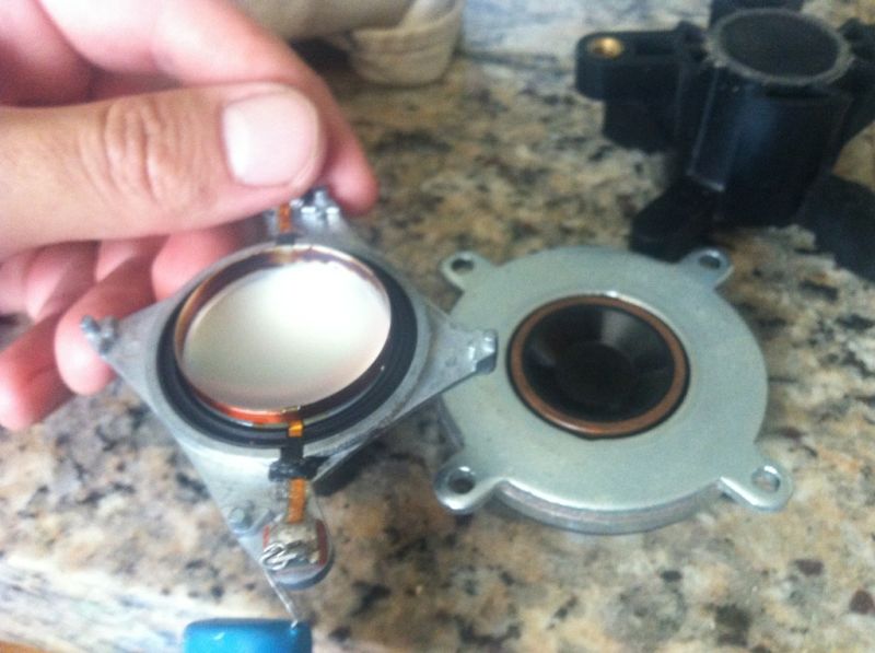
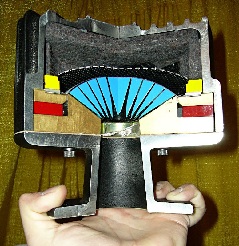
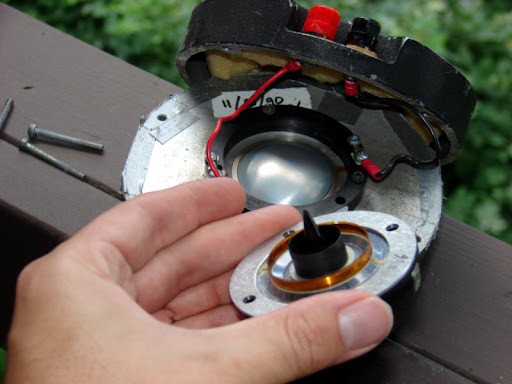
Here is a picture of a Celestion CDX1-1425 with and without the phase plug removed, and a picture of the phase plug itself. (The phase plug inserts inside a frustum, and forms the phase plug)
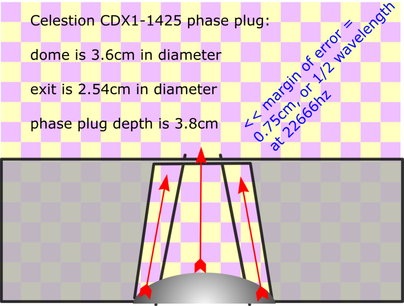

From my phase plug thread (http://www.diyaudio.com/forums/multi-way/219130-illustrated-demonstration-effect-phase-plugs.html), you'll recall that the sound of two radiators will null each other out when they're out of phase by one-half wavelength. I've coined a term for our phase plugs that I'll call our "margin of error." The margin of error is the distance at which the two radiators null each other out perfectly.
In the pic above, we see that the top of the Celestion's dome is about 0.75cm higher than the edge. This means that the sound from the top of the dome will reach your ears sooner than the sound from the edge. The phase plug on the Celestion is a simple frustum (Frustum - Wikipedia, the free encyclopedia). The frustum simply takes the energy radiated off of the diaphragm and focuses it into an area that's 2.54cm in diameter. Very simple.
We can calculate when the null will happen. Here's the formula:
speed of sound / distance / 2 =
34000cm per second / 0.75cm / 2
= 22666hz
So the pathlength difference between the tip of the dome and the edge of the dome should cause a null at approximately 22666hz. (This is just based on the phase plug, not on the Paraline.)
When we add the Paraline, the margin of error grows to about 1.75cm. If this doesn't make sense, just measure the length of the pathlength on the outside of the Paraline, then subtract the pathlength of the INSIDE of the Paraline.
In the pic I've posted above, of a 10cm Paraline, the pathlength difference is 1cm.
Using our formula again, we find that a difference of 1.75 gives us an upper limit of 9714hz. (1cm from the Paraline and 0.75cm from the phase plug of the Celestion itself.)
As Nate Hansen found, the margin of error of a plain ol' dome isn't much worse than this; for instance a 2.54cm dome has a margin of error of about 2.27cm (1.27 for the dome, 1cm for the Paraline) and it's upper limit is about 7488hz.
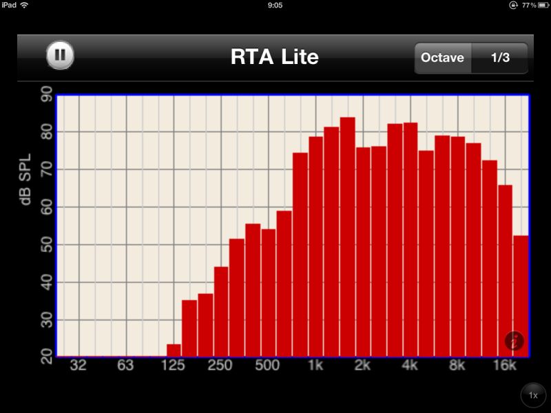
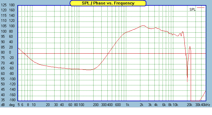
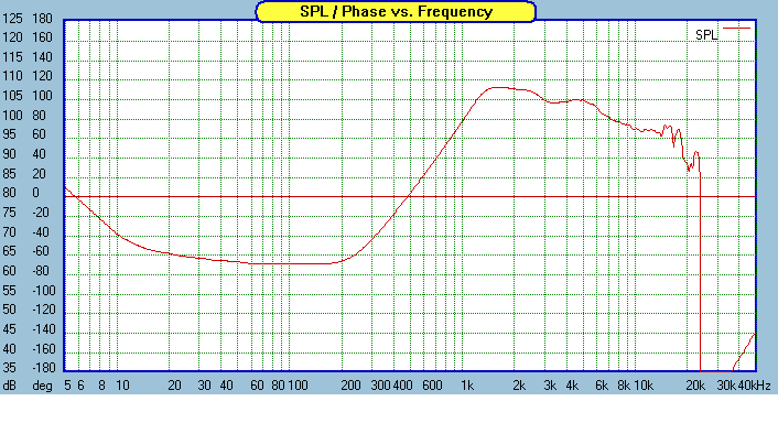
Here's a measurement of the CDX1-1425 on a Paraline. (I measured this using a simple RTA program for the iPad.)
In the graph, we see the high frequencies slowly rolling off beginning about 10khz. This isn't a 100% match with our predictions. But I think it's relatively consistent. I believe the reason that the null isn't as deep and obvious as what we see with a conventional phase plug is that the Paraline has a LOT of pathlengths. I believe this is spreading out the effect over the entire top octave. This may also explain why Nate's measurements show a series of notches:
Let me know if you have any questions about the nulls, why it happens, the geometry, etc.
At this point, you're likely wondering what will happen in the Y axis. I'll document that shortly.
Last edited:
Patrick,
I think that some of your basic assumptions about compression drivers are very off the mark in why they were designed to do what they do and how they are working. You are going to have to go way back to some of the original physics to see what it was all about. It was not to make all the wavelengths even, it doesn't hold water that this is happening. Maybe in the actual phase plug distances of the internal workings but not from the aspect of the length from the diaphragm itself. The phase plugs and extremely small air space between the diaphragm are creating refractive waves, this is the principal at work here. It is much more than just a waveguide directing the wavelengths at an equal distance. You have to go way back to Webster and Olson and a few others to read the physics, you can't compare the Paraline to the function of a true phase plug in a compression driver. You can attach a compression driver to the Paraline, but that is altogether a different animal. You are working after the function of the driver. If you want to call something a waveguide be my guest, but it is not the same animal.
I think that some of your basic assumptions about compression drivers are very off the mark in why they were designed to do what they do and how they are working. You are going to have to go way back to some of the original physics to see what it was all about. It was not to make all the wavelengths even, it doesn't hold water that this is happening. Maybe in the actual phase plug distances of the internal workings but not from the aspect of the length from the diaphragm itself. The phase plugs and extremely small air space between the diaphragm are creating refractive waves, this is the principal at work here. It is much more than just a waveguide directing the wavelengths at an equal distance. You have to go way back to Webster and Olson and a few others to read the physics, you can't compare the Paraline to the function of a true phase plug in a compression driver. You can attach a compression driver to the Paraline, but that is altogether a different animal. You are working after the function of the driver. If you want to call something a waveguide be my guest, but it is not the same animal.
Patrick,
I think that some of your basic assumptions about compression drivers are very off the mark in why they were designed to do what they do and how they are working. You are going to have to go way back to some of the original physics to see what it was all about. It was not to make all the wavelengths even, it doesn't hold water that this is happening. Maybe in the actual phase plug distances of the internal workings but not from the aspect of the length from the diaphragm itself. The phase plugs and extremely small air space between the diaphragm are creating refractive waves, this is the principal at work here. It is much more than just a waveguide directing the wavelengths at an equal distance. You have to go way back to Webster and Olson and a few others to read the physics, you can't compare the Paraline to the function of a true phase plug in a compression driver. You can attach a compression driver to the Paraline, but that is altogether a different animal. You are working after the function of the driver. If you want to call something a waveguide be my guest, but it is not the same animal.
You've noted that The phase plugs and extremely small air space between the diaphragm are creating refractive waves, this is the principal at work here. It is much more than just a waveguide directing the wavelengths at an equal distance. You have to go way back to Webster and Olson and a few others to read the physics, you can't compare the Paraline to the function of a true phase plug in a compression driver.
I think your comments may be true in a device like this:
That's a radial phase plug I believe.
But the drivers that I use don't have 'em. Celestion CDX1-1425, BMS 4540ND, BMS 4550 etc... None of them use a radial phase plug.
Here's a 4540nd compared to a conventional compression driver with a radial phase plug. Dwarfs it, no?
IMHO, Danley is right - you really have to look a the geometry all the way down to the diaphragm. So the wavefront shape and expansion will depend a lot on which compression driver is mated to the Paraline. And likely the best results will factor that into the equation. (Which is why I'm drawing these painstaking illustrations of the pathlength.)
Last edited:
Patrick,
Yes in a radial or even the so called tangerine type devices the air space between the diaphragm and surface of the phasing plug are minimal. Now if you look at the device you show and notice the center ring the distance to the center of the diaphragm and the slot is not equal from all distances. The same will hold true for a tangerine type design. There is just no way to equalize the distance over the surface of the diaphragms and any type of phasing plug, there will always be some differences in path length. In the actual throat of the phasing plug that can be true, but not from the actual diaphragm out. That is a point that I am trying to make. Now does this cause any phase cancellation or problems in the device, I wouldn't swear on this either way. I just am pointing out that this is part of the function of a true compression drivers design. Now some other cheaper devices may have a different geometry but that probably has more to do with manufacturing costs than anything else.
Yes in a radial or even the so called tangerine type devices the air space between the diaphragm and surface of the phasing plug are minimal. Now if you look at the device you show and notice the center ring the distance to the center of the diaphragm and the slot is not equal from all distances. The same will hold true for a tangerine type design. There is just no way to equalize the distance over the surface of the diaphragms and any type of phasing plug, there will always be some differences in path length. In the actual throat of the phasing plug that can be true, but not from the actual diaphragm out. That is a point that I am trying to make. Now does this cause any phase cancellation or problems in the device, I wouldn't swear on this either way. I just am pointing out that this is part of the function of a true compression drivers design. Now some other cheaper devices may have a different geometry but that probably has more to do with manufacturing costs than anything else.
The key word here guys is "approximates". I know several of us on here are very detailed and analytically minded, but we need to keep this stuff in perspective. I've built so many things I have a feel for what is important and what can be stretched a little bit. ...
... The high frequency rolloff of a conical horn (and a Paraline is a conical horn) ...
JLH, this is a perfect illustration of my point. The profile does matter. If you get it wrong, everything you derive from it is also wrong, such as the profile of a Unity-style horn to extend a Paraline. You may have the experience to know "what is important and what can be stretched a little bit", but "several of us on here" don't have your experience and knowledge and depend on the advice of those such as yourself to guide us in the right direction.
Don Hill,
I agree with you 100% on this. Everything we design is a decision on what factors we can fudge, which are the most important and what compromises we can reasonably get away with. I have nothing against the Paraline, I actually think it is a rather cleaver way to foreshorten a waveguide. But like you I do think that the shapes are changing the response curves of the device. How well this would work with and exponential expansion rate in the horn flare verses a conic section I have not seen yet. I would conjecture that there would be a definite difference in both the dispersion and frequency response of the final outcome. I also can see how you could vary the cross-sectional dimension to create a more optimum expansion rate but at a much more difficult method of production. These are just observations from me watching and learning about something different. And yes I do look at all the little details, I just can't help myself.
Steven
JLH, this is a perfect illustration of my point. The profile does matter. If you get it wrong, everything you derive from it is also wrong, such as the profile of a Unity-style horn to extend a Paraline. You may have the experience to know "what is important and what can be stretched a little bit", but "several of us on here" don't have your experience and knowledge and depend on the advice of those such as yourself to guide us in the right direction.
I try the best I can to help people, but I can't always explain everything I know. Many times it can't even be put into words. I was in your shoes nearly some 20 years ago when I read one of Bruce Edgar's first horn articles. Knowledge takes time.
I totally don't get that drawing. What's the last picture (rightmost). ?
The mouth section.
Patrick,
Yes in a radial or even the so called tangerine type devices the air space between the diaphragm and surface of the phasing plug are minimal. Now if you look at the device you show and notice the center ring the distance to the center of the diaphragm and the slot is not equal from all distances. The same will hold true for a tangerine type design. There is just no way to equalize the distance over the surface of the diaphragms and any type of phasing plug, there will always be some differences in path length. In the actual throat of the phasing plug that can be true, but not from the actual diaphragm out. That is a point that I am trying to make. Now does this cause any phase cancellation or problems in the device, I wouldn't swear on this either way. I just am pointing out that this is part of the function of a true compression drivers design. Now some other cheaper devices may have a different geometry but that probably has more to do with manufacturing costs than anything else.
B&C DE250 has a phase plug like this. (A radial phase plug.)

Here's what it looks like if you open it up.
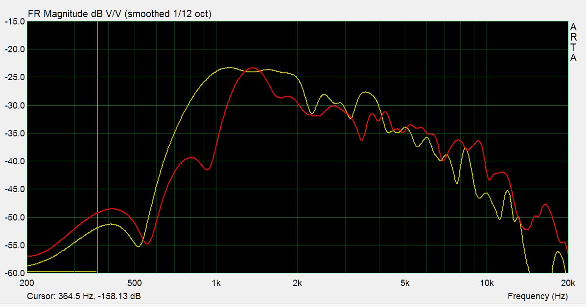
Here's the frequency response
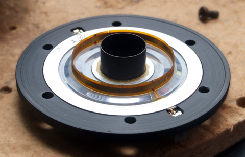
Celestion CDX1-1425 looks like this if you take it apart
Phase plug looks like this. (Simple frustum)
Here's the frequency response
The DE250 clearly has a more sophisticated phase plug than the Celestion. Yet the Celestion plays higher.
I'd argue that the 'perfection' of the radial phase plug is creating a deeper null at 20khz, but that the 'imperfection' of the Celestion phase plug is simply spreading out the peaks and dips. So basically the Celestion phase plug isn't perfect, but it's close enough, and when combined with a much smaller radiating surface you end up with more extended response.
A lot of this goes back to the arguments that Geddes has had in the 'Geddes on waveguides' thread in regards to whether a dome tweeter can/should be used with a waveguide.
I'd argue that plain ol' domes are acceptable *if* you factor in the geometry, and this generally means that a much smaller diaphragm goes a long way, and flattening it helps too.
Patrick,
I am not going to get into it with Geddes on this forum, I have a big beef with him so I will leave that out. But it goes without saying that if you lower the moving mass it will be much easier to excite the diaphragm at higher frequencies. The smaller diaphragm will also have a limit in the lower pass band due to limited excursion of the diaphragm and that is one of the tradeoffs that any driver designer will have to make. You can move the frequency up or down but each device has a limited bandpass that it works well in before mass or size takes over. As far as using a dome tweeter in a horn that has a few other dependencies. An aluminum dome tweeter vs a soft dome is one of these tradeoffs as the metal dome is much stiffer than the soft dome and will not as easily deform, also many soft domes are very porous and there will be air leakage through the material. If the waveguide does not have a compression, meaning a reduction in area compared to the dome diameter I don't think that there is much problem with a waveguide in front of either one of these types of dome tweeters, but then you do have to deal with the horn gain at the cutoff frequency verses the high frequency output. I have done this with both materials and even with inverted dome titanium domes. They can all work given the one problem of falling frequency response with higher frequencies. I am not a proponent of the inverted dome though, they have other problems that are not spoken of. Just a marketing reason to do that and be different.
I am not going to get into it with Geddes on this forum, I have a big beef with him so I will leave that out. But it goes without saying that if you lower the moving mass it will be much easier to excite the diaphragm at higher frequencies. The smaller diaphragm will also have a limit in the lower pass band due to limited excursion of the diaphragm and that is one of the tradeoffs that any driver designer will have to make. You can move the frequency up or down but each device has a limited bandpass that it works well in before mass or size takes over. As far as using a dome tweeter in a horn that has a few other dependencies. An aluminum dome tweeter vs a soft dome is one of these tradeoffs as the metal dome is much stiffer than the soft dome and will not as easily deform, also many soft domes are very porous and there will be air leakage through the material. If the waveguide does not have a compression, meaning a reduction in area compared to the dome diameter I don't think that there is much problem with a waveguide in front of either one of these types of dome tweeters, but then you do have to deal with the horn gain at the cutoff frequency verses the high frequency output. I have done this with both materials and even with inverted dome titanium domes. They can all work given the one problem of falling frequency response with higher frequencies. I am not a proponent of the inverted dome though, they have other problems that are not spoken of. Just a marketing reason to do that and be different.
The mouth section.
Sorry to seem dense, but I'm still confused and really want to follow this. I marked the first 2 parts of the drawing with how I think a positive going pressure would expand outward from a CD at center. Maybe I don't get both the third and fourth. Where is the pressure expanding in those?

And does the third part represent another fold again (the folds of the second drawing meeting, then folding back?) or are they just from the first fold overlapping somehow to get that?
Where does the pressure wave exit in the fourth?
Sorry again, everytime I see another sketch other than the line source-making paraline, I find I don't really understand.
Edit:
Here's a better picture with the left side starting and right side starting internal pressure waves in different colors (red and green). What are they in the 3rd and 4th parts?
Last edited:
- Home
- Loudspeakers
- Multi-Way
- Square Pegs