The Endeavour, a 3.5 way active speaker concept
After a few stabs at dipoles in the last two years, I've recently worked on an active speaker concept I call Endeavour – and it really is, since I'm still very much a beginner (although I've learned a lot in theory from you all). By now, it's concept only, and before going any further, I'd like to hear your comments on it!
It’s a ported 3.5 way construction that I tried to optimize for the following design goals:
I tried to achieve these goals by the following design choices:
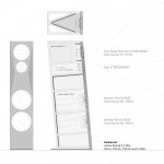
Outer dimensions (W*H*D): 21cm * 99.5cm * 30cm
Drivers used:
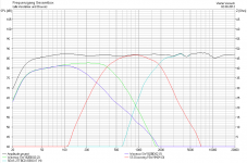
Acoustical crossover points (ca.): 270 Hz, 370 Hz, 1.8 kHz
Crossovers are LR2 for the enforcement woofer and LR4 for W-M and M-T.
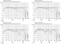
I simulated the concept in Boxsim as good as I could, using published data from Wavecor, Scan Speak and http://http://www.lautsprecherbau.de/. Tilting had to be emulated by placing the drivers "behind" the front baffle, and digital notch filters had to be simulated by analog rejection circuits. The stuffing was configured to match the ~15% volume extension I found in online resources for the kind of absorption I'm planning to use. The results (individual and combined frequency responses on axis, horizontal and vertical off axis responses) are attached.
I didn't optimize the bass for maximum linear extension because the speakers wouldn't be too far from the back walls and I tried to limit excursion below 30 Hz; but that could easily be changed by different digital filters, of course.
How does the concept look to you? Any obvious faults or mistakes? Any details I haven't thought of or trade-offs I should rethink?
I'm especially uncertain about phase tracking between the drivers, especially because the driver arrangement is a bit unorthodox.
Looking forward to your feedback!
After a few stabs at dipoles in the last two years, I've recently worked on an active speaker concept I call Endeavour – and it really is, since I'm still very much a beginner (although I've learned a lot in theory from you all). By now, it's concept only, and before going any further, I'd like to hear your comments on it!
It’s a ported 3.5 way construction that I tried to optimize for the following design goals:
- even and wide lateral dispersion (Toole-style)
- reduced baffle diffraction
- minimal floor bounce cancellation
- good vertical polar response above the speaker at least for angles up to 30°
- minimized internal reflections, resonances, and enclosure vibrations
- small speaker size while preserving full bandwith for music reproduction
- listening distance between 2 and 2.5m
- adaptability to room and placement constraints
I tried to achieve these goals by the following design choices:
- combine a 5" midrange with a waveguided tweeter or more precisely a tweeter with a diffraction lense
- facet the upper half of the front baffle
- place the floor bounce frequencies as far in the speakers' stop bands as possible, while still maintaining driver distances below 1/2 wavelength at XO frequencies
- reverse the usual MT arrangement to TM, thus reducing vertical lobing above the speaker
- choose 6.5" bass drivers suited for small enclosures
- use a second bass driver as a 0.5 way for enforcement
- use an 18mm plywood/4mm bitumen/3mm HDF sandwich enclosure, but only average bracing
- use absorption on the back- and sidewalls plus around 5" of porous absorption to eliminate the longitudinal standing wave resonance of the bass chamber
- tilt the box slightly upward
- cram 4 150W switching amplifiers and an SMPS into each box
- use an external MiniDSP 4x10 Hd as a digital preamp and crossover box
Outer dimensions (W*H*D): 21cm * 99.5cm * 30cm
Drivers used:
- 2 * Wavecor SW 182 BD 02 with dual 2" ports
- Scan Speak 15W/8424G00
- Seas 27TBCD/GB-DXT
Acoustical crossover points (ca.): 270 Hz, 370 Hz, 1.8 kHz
Crossovers are LR2 for the enforcement woofer and LR4 for W-M and M-T.
I simulated the concept in Boxsim as good as I could, using published data from Wavecor, Scan Speak and http://http://www.lautsprecherbau.de/. Tilting had to be emulated by placing the drivers "behind" the front baffle, and digital notch filters had to be simulated by analog rejection circuits. The stuffing was configured to match the ~15% volume extension I found in online resources for the kind of absorption I'm planning to use. The results (individual and combined frequency responses on axis, horizontal and vertical off axis responses) are attached.
I didn't optimize the bass for maximum linear extension because the speakers wouldn't be too far from the back walls and I tried to limit excursion below 30 Hz; but that could easily be changed by different digital filters, of course.
How does the concept look to you? Any obvious faults or mistakes? Any details I haven't thought of or trade-offs I should rethink?
I'm especially uncertain about phase tracking between the drivers, especially because the driver arrangement is a bit unorthodox.
Looking forward to your feedback!
Attachments
Last edited:
Member
Joined 2009
It looks like an awesome and well thought-out project. I can only think of 2 small things that I would do differently.
3.5 designs usually roll off the helper woofer with a 1st order slope. That will ensure the woofers combine with a coherent phase. The roll off on the helper woofer can be strategically placed to compensate for the baffle step loss.
I see no reason to tilt the speaker. The sloping baffle will not help time-align and since you have the tweeter under the woofer can make matters worse. The DXT tweeter sits further back than regular tweeters so it probably doesn't need to be time-aligned with the mid.
With careful fine-tuning of the crossover frequencies and driver spacing you should be able to achieve exemplary directivity. I assume that you have measurement equipment and the miniDSP will make that process easy.
Good luck!
Thanks Boris!
That's a very good point – I didn't think of the 2nd order induced phase shift.
I see your point – in fact, the reason for tilting the speaker back wasn't time alignment (I could that with the miniDSP anyway if needed at all). I pointed the DXT's 0° axis slightly upwards to the intended listening position in order to keep speaker height as small as possible. But looking at the vertical response graphs, having the listening axis a few degrees above 0° shouldn't be problematic anyway...
Yes, I have. Thanks a lot!
3.5 designs usually roll off the helper woofer with a 1st order slope. That will ensure the woofers combine with a coherent phase. The roll off on the helper woofer can be strategically placed to compensate for the baffle step loss.
That's a very good point – I didn't think of the 2nd order induced phase shift.
I see no reason to tilt the speaker. The sloping baffle will not help time-align and since you have the tweeter under the woofer can make matters worse. The DXT tweeter sits further back than regular tweeters so it probably doesn't need to be time-aligned with the mid.
I see your point – in fact, the reason for tilting the speaker back wasn't time alignment (I could that with the miniDSP anyway if needed at all). I pointed the DXT's 0° axis slightly upwards to the intended listening position in order to keep speaker height as small as possible. But looking at the vertical response graphs, having the listening axis a few degrees above 0° shouldn't be problematic anyway...
With careful fine-tuning of the crossover frequencies and driver spacing you should be able to achieve exemplary directivity. I assume that you have measurement equipment and the miniDSP will make that process easy.
Good luck!
Yes, I have. Thanks a lot!
Second iteration
Following Boris's suggestions and some feedback on HTGuide, I changed two aspects of the design:
a) I removed the tilt, swapped the MT arrangement, and re-simmed. And voilà: Vertical dipersion still meets my goal of being reasonably smooth up to 30° upwards, and downward dispersion got a bit better in the first 30°. Plus construction got a whole lot simpler!
b) I changed the LP slope of the helper woofer to first order, but added an additional LR2 filter higher up to bring the woofer down in the higher midrange where it exhibits a rather nasty breakup peak. The resulting on axis response is a lot smoother than before.
The changed arrangement brings up the mid's SPL at its floor bounce frequency only 2-3 dB (and it's still 12 dB down at that point), so all in all I'd say: Improvements on all fronts!
Next up: Trying a 2nd order MT configuration to see if I can get better power response.
Thanks for the feedback so far – I'll keep you posted!
Attachments
Last edited:
Hi Wowo,
So far your simulations look very good. You mention phase tracking and I assume your simulator will allow plotting of phase of the individual sections as would reveal this. At the same time we can infer that it is very good since the summed response is so smooth and also because the tweeter crossover has 6dB sum gain (even improved on the second version after good suggestions from Boris).
I think there is a missed opportunity to totally remove floor bounce with this design. You have calculated the floor bounce frequencies (first notch frequency?) but you seem to have placed the crossover frequency right at the bounce frequency of the mids. If your simulater allows, you could sim a second system below the reflecting floor and see the reflection effects. Pushing the woofers down in the cabinet would raise their floor bounce freq. You might then be able to cross between woofer and mid bounce frequency and remove all effects.
At least worth a sim.
Can you translate some of the German? Hinter is rearward response?
David S
Thanks for the detailed feedback, David!
Yes, I began playing around with the phase plots after posting my initial version, and at the moment I'm trying out different baffle slopes to get the required time delay for the tweeter physically instead of electronically. I think I'm slowly getting the hang of the aligment/delay/phase/FR interdependencies involved.
Concerning the floor bounce: Yes, the frequencies shown are for the first notches. Since my simulator (Boxsim) doesn't allow me to sim more than one system, I used the Boxycad spreadsheet (http://audio.claub.net/boxycad2.xls) and the lobing calculator at mh-audio.nl - Home to arrive at the ideal XO frequency – but I haven't redone the calculations since changing the driver arrangement. Will do that to see if I can realize your suggestion. Thanks!
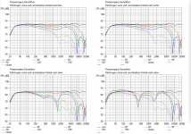
As for the German: The graphs (clockwise from top left) are for off-axis response to the left, right, downward, and upward; and "hinten" indeed means rearward response.
Yes, I began playing around with the phase plots after posting my initial version, and at the moment I'm trying out different baffle slopes to get the required time delay for the tweeter physically instead of electronically. I think I'm slowly getting the hang of the aligment/delay/phase/FR interdependencies involved.
Concerning the floor bounce: Yes, the frequencies shown are for the first notches. Since my simulator (Boxsim) doesn't allow me to sim more than one system, I used the Boxycad spreadsheet (http://audio.claub.net/boxycad2.xls) and the lobing calculator at mh-audio.nl - Home to arrive at the ideal XO frequency – but I haven't redone the calculations since changing the driver arrangement. Will do that to see if I can realize your suggestion. Thanks!
As for the German: The graphs (clockwise from top left) are for off-axis response to the left, right, downward, and upward; and "hinten" indeed means rearward response.
Update!
As suggested on the HTGuide forum, I redid my math to see how a sloped baffle might help with time alignment of the drivers:

I arrived at a 6° slope that ensures good phase tracking and would thus in principle allow the Endeavour to be driven passively and without electrical time alignment. (Plus, the more complicated construction is back! Yay!)

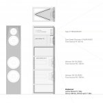
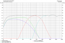
Furthermore, I followed David's suggestions concerning floor bounce cancellation avoidance: I moved the woofers quite a bit lower and recalculated the target W-M crossover frequency, the main constraint being keeping W-M distance below 1/2 wavelength at XO frequency, while at the same time crossing over at the geometric mean of the W and M floor bounce frequencies (first notch). For the resulting driver responses, see the FR graph:


One drawback of the current iteration is increased vertical lobing above listening height (at least in the M-T crossover area.)
This leads directly to the questions I hope you can help me with:
Thanks in advance – I hope I'm nearing actual build planning, so keep the feedback coming!
P.S. I attached a more "realistic" rendering of the Endeavours' current incarnation – I think I like the looks, do you?

As suggested on the HTGuide forum, I redid my math to see how a sloped baffle might help with time alignment of the drivers:
I arrived at a 6° slope that ensures good phase tracking and would thus in principle allow the Endeavour to be driven passively and without electrical time alignment. (Plus, the more complicated construction is back! Yay!)
Furthermore, I followed David's suggestions concerning floor bounce cancellation avoidance: I moved the woofers quite a bit lower and recalculated the target W-M crossover frequency, the main constraint being keeping W-M distance below 1/2 wavelength at XO frequency, while at the same time crossing over at the geometric mean of the W and M floor bounce frequencies (first notch). For the resulting driver responses, see the FR graph:
One drawback of the current iteration is increased vertical lobing above listening height (at least in the M-T crossover area.)
This leads directly to the questions I hope you can help me with:
- Would using a 3rd order Butterworth instead of a 4th order LR for M-T XO help with upwards vertical dispersion? If so, what would be the trade-offs involved?
- What would be the minimum depth for the front baffle faceting to be useful? I sketched and simmed a 25mm baffle – would that be enough in your opinion?
- When using a constrained layer/bitumen sandwich approach to enclosure damping, how thick should each layer (plywood, bitumen, HDF) be in your opinion?
Thanks in advance – I hope I'm nearing actual build planning, so keep the feedback coming!
P.S. I attached a more "realistic" rendering of the Endeavours' current incarnation – I think I like the looks, do you?
Hi wowo,
nice driver choice for M and T. If I were to build a box speaker I would certainly think about the two as well.
1. Would using a 3rd order Butterworth instead of a 4th order LR for M-T XO help with upwards vertical dispersion? If so, what would be the trade-offs involved?
=> A BW3 tilts the combined beam 15° up or down depending on the polarity of the drivers. I am not sure about the height of your couch but I guess you will be better off with a straight beam and steeper slopes of the LR4.
2. It looks as if the facetting could be sufficient but only measurements will tell the truth.
Some more comments, maybe you have simulated the following already and put aside as non-working. If not, maybe worth a thought:
a. I would try to flank the Seas with two drivers. With the Discovery 15 you will certainly not achieve a clean D'Appolito but a floor bounce in the mid could be minimized. If the 15 is too big, there is a 12cm discovery as well.
b. Then I would cross over to the woofers a bit lower and turn the helper woofer into a 2nd real one. Should be no issue at around 200..250 Hz
c. I would move those woofers to the side and make the front as slim as possible to preserve the horizontal dispersion as far up as possible. Of course the directionality will need to be matched between M and T.
d. I would not tilt the speaker either and use a cross over with a "straight" beam and sufficient steepness like LR4.
These are my suggestions. Take what you like and toss the rest
Good luck
Oliver
Last edited:
Thanks for the detailed feedback, Oliver!
That's actually pretty close to the design I considered before the current one but scrapped before simulating. For me, the following points seemed problematic:
Maybe I'm off the mark with some of those points – any thoughts?
a. I would try to flank the Seas with two drivers. With the Discovery 15 you will certainly not achieve a clean D'Appolito but a floor bounce in the mid could be minimized. If the 15 is too big, there is a 12cm discovery as well.
b. Then I would cross over to the woofers a bit lower and turn the helper woofer into a 2nd real one. Should be no issue at around 200..250 Hz
c. I would move those woofers to the side and make the front as slim as possible to preserve the horizontal dispersion as far up as possible. Of course the directionality will need to be matched between M and T.
d. I would not tilt the speaker either and use a cross over with a "straight" beam and sufficient steepness like LR4.
That's actually pretty close to the design I considered before the current one but scrapped before simulating. For me, the following points seemed problematic:
- For a "real" D'Appolito arrangement, even using a 12W or another 4" driver with the DXT nd cutting back as much of their flanges as possible would result in a required crossover frequency of about 1.2 kHz – not doable with the DXT. And I didn't find any tweeter with comparable dispersion control and a smaller diameter.
- One possibility to get around this would have been to use a coax, but the only ones with smooth FR on and off axis I'm aware of are the current KEF UniQ drivers, which are quite hard to get for DIY purposes.
- Lowering the W-T crossover point to 200-250 Hz as needed for a side-firing woofer arrangement would mean that I'm crossing over in the region of the mid floor bounce cancellation, and if I don't have a clean D'Appolito design, I doubt if the combined effect of XO and vertical dispersion control would be enough to mitigate the floor bounce effect.
Maybe I'm off the mark with some of those points – any thoughts?
Always welcome.
It is of course your choice but maybe worth another simulation evening.
I know, but history has proven that even non-text book style MTM configurations result in a reduced but controlled vertical dispersion. That needs simulation, though. Also, many of those "proven" designs use LR4 filters instead of the text book BW3 filters and as far as I know, Joe himself is not really concerned about the design freedomFor a "real" D'Appolito arrangement, even using a 12W or another 4" driver with the DXT nd cutting back as much of their flanges as possible would result in a required crossover frequency of about 1.2 kHz – not doable with the DXT. And I didn't find any tweeter with comparable dispersion control and a smaller diameter.
It is of course your choice but maybe worth another simulation evening.
It is of course your choice but maybe worth another simulation evening.
That it definitely is.
It would be great if the Seas data were available in Boxsim so that one could see the effect of the diffraction lense in this MTM arrangement. But I think the data is not available, right ?
I also meant to say: In the end the vertical response does not have to be perfect. Horizontal is much more important. So it would just be nice to avoid or minimize the floor bounce. But maybe you have some heavy carpet in front of the speakers. Then it would be a notch less important.
I also meant to say: In the end the vertical response does not have to be perfect. Horizontal is much more important. So it would just be nice to avoid or minimize the floor bounce. But maybe you have some heavy carpet in front of the speakers. Then it would be a notch less important.
Last edited:
I've used the measurement data from here: http://www.lautsprecherbau.de/user/design/stories/Artikel/2011/Juli/Excel22DXT/27TBCD__DXT.zip as well as an SplTrace of the data published by SEAS, which seems to be good enough for the on-axis simulation.
As there is no possibility to correctly simulate the lense (or generally, waveguides) in Boxsim, I emulated the general effect by enlarging the sound radiating area, but this obviously doesn't get correct or even near correct results for off-axis FR. A discussion of waveguides and Boxsim off-axis results can be found somewhere in this thread: http://www.visaton.de/vb/showthread.php?t=22618
As there is no possibility to correctly simulate the lense (or generally, waveguides) in Boxsim, I emulated the general effect by enlarging the sound radiating area, but this obviously doesn't get correct or even near correct results for off-axis FR. A discussion of waveguides and Boxsim off-axis results can be found somewhere in this thread: http://www.visaton.de/vb/showthread.php?t=22618
Last edited:
A fresh start
Hey all,
after a hiatus of a few months, I've reconsidered the design decisions of my Endeavour project and entered a second design iteration which I'd love to get your feedback on.
First of all, following 6.283's advice, I modeled a pseudo-D'Appolito MTM arrangement using small Discovery 10F drivers as mids in order to get as small a CTC distance as possible while keeping the DXT tweeter. The result was horrendous suckouts in the vertical plane which convinced me not to pursue this avenue further – although the "forward sounding character" of such an arrangement might appeal to some… (6.283, I'm following your recent design efforts at Kierkegaard - Kontrolliertes horizontales & vertikales Bündelungsmaß - DIY-HIFI-Forum with great interest – the combination of even smaller mids, a fullrange driver as tweeter and a very low XO frequency seems a promising path!)
I then reconsidered midrange driver, baffle width and woofer section, starting with the following assumptions:
Following this, the design I arrived at differs from the first approach in the following aspects:
The preliminary results are these:

(Construction sketch)

(Driver and summed FR)

(horizontal and vertical response plots)
Please ignore tweeter behaviour at angles > 0° since the DXT waveguide can't be modeled correctly in BoxSim.
My main concern now is power response at W-M XO which isn't as smooth as I hoped it would be – any hints on that?
And apart from that: Any other feedback?
Hey all,
after a hiatus of a few months, I've reconsidered the design decisions of my Endeavour project and entered a second design iteration which I'd love to get your feedback on.
First of all, following 6.283's advice, I modeled a pseudo-D'Appolito MTM arrangement using small Discovery 10F drivers as mids in order to get as small a CTC distance as possible while keeping the DXT tweeter. The result was horrendous suckouts in the vertical plane which convinced me not to pursue this avenue further – although the "forward sounding character" of such an arrangement might appeal to some…
(6.283, I'm following your recent design efforts at Kierkegaard - Kontrolliertes horizontales & vertikales Bündelungsmaß - DIY-HIFI-Forum with great interest – the combination of even smaller mids, a fullrange driver as tweeter and a very low XO frequency seems a promising path!)I then reconsidered midrange driver, baffle width and woofer section, starting with the following assumptions:
- A smaller mid could be used to reduce CTC distance between tweeter and midrange since max. SPL is limited by tweeter and woofer.
- Front wall reflections should be reduced down to at least 500 Hz, i.e. in the range where our hearing is most acute. Cardioid solutions were ruled out because of implementation complexity and uncertainty about behaviour near walls (cf. http://www.diyaudio.com/forums/mult...doid-midbass-minimum-distance-front-wall.html).
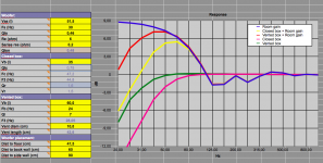
- Boundary effects/room gain simulations showed that a CB configuration would yield the flattest bass response in room (see first attachment); at the same time, impulse response could be optimized by switching to CB.
- Going 3-way instead of 3.5-way would reduce cost and complexity.
Following this, the design I arrived at differs from the first approach in the following aspects:
- Scan Speak Discovery 12w midrange driver instead of 15w, which also matches the DXT's directivity at XO frequency better.
- Baffle width expanded to 26cm, resulting in a baffle step center frequency of 442 Hz; accompanied by larger chamfers to avoid increased edge diffraction effects.
- Bass is now handled by a single 8" long-throw woofer (TIW 200 XS - 8 Ohm) in a 35 l closed box per side; possible bass extension by adding a Linkwitz transform to a suitable Fc.
- W-M arranged to achieve a good compromise between floor bounce reduction and driver integration.
- W-M XO moved to 500 Hz (geometric mean of first woofer and midrange floor bounce nulls).
The preliminary results are these:
(Construction sketch)
(Driver and summed FR)
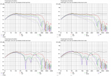
(horizontal and vertical response plots)
Please ignore tweeter behaviour at angles > 0° since the DXT waveguide can't be modeled correctly in BoxSim.
My main concern now is power response at W-M XO which isn't as smooth as I hoped it would be – any hints on that?
And apart from that: Any other feedback?
Attachments
Hi Wowo,
I have recently asked myself what has become of this project !
Too bad that it did not work out with the MTM. What cross-overs did you use to simulate the MTM configuration and also this draft?
Anyway, the horizontal response is more important than floor bounce issues down in that freq. range. If you push the mid woofer down to 200Hz then the sub will operate in the modal region of the room and there is simply no floor bounce anymore to speak of, which only leaves the one of the midrange driver.
I would also not worry too much about those room gain calculations. I think they are crude at best if at all applicable to reality.
What drives the F-3 of the woofer is the F of first and second order room modes and the excursion capability of the diver (and of course placement of the box).
So this one has plenty of excursion and could easily be driven down to 25...30 Hz. Use a corrected Qt of 0.5 in CB, stay away from the 1st and 2nd order room modes also by placement (0.25 x room width for 2nd order) and enjoy. It won't get any better than this with two integrated woofers.
Here is the link to my latest project again in English for everybody, who is interested:
Kierkegaard
TMT experiments
Thanks for the feedback, 6.283! I've attached the sim I've done using Visaton's B80 as mid drivers (comparable in size and performance to the 10F). I used 3rd order Butterworth filters; the suckout affects the midrange and, combined with some off-axis flare above that region, leads to a quite uneven power response.
BUT: I've just begun to play around with 4th order LR filters instead of the Butterworth alignment, and things are beginning to look much better in that configuration! Will keep you posted.
Attachments
TMT experiments, part II
And these are the results of a quick reconfiguration along 6.283's lines (TMT, woofer near floor and crossed low), this time with a 4th LR alignment for mid and tweeter (and 2nd order for woofer and mid).
Now I get a quite large vertical listening window, together with a very even power response an quite smoothly rising directivity. Don't know why I didn't try and change the crossover alignment last time I did these simulations…

(individual and summed FR)

(horizontal and vertical response plots)

(directivity)
And these are the results of a quick reconfiguration along 6.283's lines (TMT, woofer near floor and crossed low), this time with a 4th LR alignment for mid and tweeter (and 2nd order for woofer and mid).
Now I get a quite large vertical listening window, together with a very even power response an quite smoothly rising directivity. Don't know why I didn't try and change the crossover alignment last time I did these simulations…
(individual and summed FR)
(horizontal and vertical response plots)
(directivity)
- Status
- This old topic is closed. If you want to reopen this topic, contact a moderator using the "Report Post" button.
- Home
- Loudspeakers
- Multi-Way
- Sanity check on my Endeavour project