Hello chaps.
Could anyone tell me if the image below looks ok regarding the placement of inductors please in my crossovers? I know this has been covered before but in this case I am mixing an Iron core and air core inductors which may be different.
L1 is an TX iron core (Autoformer)
L2 is air cored
L3 is air cored
Many thanks
![IMGDEAD]](/community/proxy.php?image=http%3A%2F%2F%5BIMGDEAD%5Dhttps%3A%2F%2Fi457.photobucket.com%2Falbums%2Fqq295%2Fmusical_submarine%2FCrossover_dia.jpg%5B%2FIMGDEAD%5D&hash=3422bdaa5b6771981dadfb654a22ab41)
Could anyone tell me if the image below looks ok regarding the placement of inductors please in my crossovers? I know this has been covered before but in this case I am mixing an Iron core and air core inductors which may be different.
L1 is an TX iron core (Autoformer)
L2 is air cored
L3 is air cored
Many thanks
in order for anyone to help, physical dimensions are helpful.
Hi, cheers... OK, I've not got the dimensions of the air cores as yet but will get them soon. As a rule of thumb am I on the right track? It's the TX core one that is throwing me.
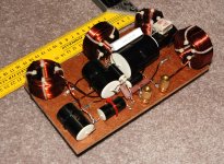
Along the lines of what David said, here is how I did it with mine.
The trick that I read was to make sure if you look through the centre of any inductor you can't see another one") Also distance helps ideally 20cm between two similarly aligned coils (I don't quite get there).
Also distance helps ideally 20cm between two similarly aligned coils (I don't quite get there).
Tony.
The trick that I read was to make sure if you look through the centre of any inductor you can't see another one
Also distance helps ideally 20cm between two similarly aligned coils (I don't quite get there). Tony.
Attachments
Someone pointed this out to me once and I found it extremely helpful.
Placement of coils in crossover networks
Placement of coils in crossover networks
Just a little bit of theory, if anyone is interested, about mutual inductance.
Lets say we have two inductors each with 100 turns of wire and each with an inductance of 1 millihenry. If we put them in series, not too close together, and measure their inductance we'll see the sum of the two inductances or 2.0 mH. Now lets take the 100 turns off of one coil and wind them onto the other. We can add some copper if we need to to get to 200 turns total. Measure this new bigger inductor and we see that rather than 2.0 mH we now have 4.0! The inductance quadrupled. We can state a rule of thumb that inductance of a given form factor will go up in proportion to turns squared: 2 times the turns gives 4 times the inductance.
The difference between 2 individual and separated inductors and the single combined inductor is called mutual coupling. We could probably just take the original 2 inductors and place them touching side by side and get pretty close to the 4 mH.
Now the orrientation makes a difference. If we have the two inductors side by side and twist one of them 180 degrees we will se the total series inductance fall to less than the sum of the two. It might even approach 0 mH. This gives us a way to measure the mutual inductance. We can connect the coils in one orrientation and measure, then connect with one coil reversed and measure again. The difference is 2 x M the mutual inductance. If two coils are sufficiently far apart then both orrientations give the same reading. L1 + L2 +M is the same as L1 + L2 - M when M is 0. If we see no difference with two series connected inductors as we change connections then we have spaced or orriented them adequately.
Since the winding direction can make a difference you will sometimes see inductors or transformers with a dot at one end of the winding, to remind you to connect in the right orrientation. I have seen crossover networks where most measured good but a number had a consistant error in response. It was because a pair of coils had significant coupling and they were not being consistantly orriented in the PC board. That is, the starting end of the winding was sometimes at a particular terminal and sometimes reversed. (So sometimes we had +M and sometimes -M).
Mutual coupling can also give odd response effects with a stop band that falls for a bit and then nulls and starts to rise. This is more often the case when the inductors are in different network sections.
Finally a picture of how old time radios took advantage of this. The variometer let you turn a second coil within an outer coil. As the angle varied you could swing over a large range of inductance with the two inductances both adding and, at other angles, subtracting.
David S.
Attachments
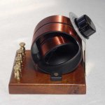
The variometer let you turn a second coil within an outer coil. As the angle varied you could swing over a large range of inductance with the two inductances both adding..
I think I want one, even if it's just to put on the mantlepiece and admire.
I've always, without knowing exactly why, made an effort to always connect my coils as you say. I'm not sure if it's right, but I use the "in / start" as the end closest to the center and the "out" as the other.
As for that variable inductor, couldn't that be something useful for crossover experimentation, or do you think it'd have ill effects? It looks like a simple thing to make.
As for that variable inductor, couldn't that be something useful for crossover experimentation, or do you think it'd have ill effects? It looks like a simple thing to make.
That is an RF coil - the inductance is probably too low for audio work - though it might be interesting to try to build one for audio.As for that variable inductor, couldn't that be something useful for crossover experimentation, or do you think it'd have ill effects? It looks like a simple thing to make.
As for that variable inductor, couldn't that be something useful for crossover experimentation, or do you think it'd have ill effects? It looks like a simple thing to make.
You can certainly use the method for a quick way to find the right value for a network. For example, connect a pair of .5 or 1.0 mH inductors in series and apply it as the primary L in series with a woofer. The orientation and spacing of the two inductors will swing the combined L from nearly 4 times the single value to near 0. With an RTA you could zoom in on the best value pretty quickly, then replace it with a single inductor of matching measured value.
You can also do the same with an iron core inductor if you can slide the core in and out. Usually you can get about a 3 to 1 swing which will let you dial in the best value.
As to the question of winding direction, it makes no difference at all to the signal but is only a factor if multiple inductors are interacting. Air core inductors have no known distortion mechanisms and the iron core ones have only symmetical (odd order) distortion, so connect either way.
David S.
As to the question of winding direction, it makes no difference at all to the signal but is only a factor if multiple inductors are interacting. Air core inductors have no known distortion mechanisms and the iron core ones have only symmetical (odd order) distortion, so connect either way.
David S.
I suppose tho that being consistent in which end you choose as the signal in would be a better choice, even if the actual direction is unimportant, I suppose in that case whether the coil is laid RH( Clockwise) or LH(Counter-clockwise) is also of little or no significance
- Status
- This old topic is closed. If you want to reopen this topic, contact a moderator using the "Report Post" button.
- Home
- Loudspeakers
- Multi-Way
- inductor placement clarification