Hello all,
I have a pair of AR93s speakers that I am restoring. I have refoamed the woofers and mid-range drivers, and am now working on the crossovers. I want to draw up a schematic of the crossover, and would like help making sure that it is drawn correctly. I am a complete beginner at drawing schematics, and I am unfamiliar with the basics of electricity flow in a circuit. I could find no schematics for the AR93s crossover on the internet, and would like to make a good one to share.
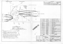
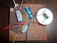
I have examined the actual crossover taken from the speaker, and have drawn up a schematic that shows the connections pretty accurately. I also found a great engineering drawing of the crossover from the library at the Classic Speaker Pages. This drawing appears to be authentic, from Acoustic Research, and exactly matches the crossover from my speaker. This drawing, and many others for AR speakers, can be found here:
http://www.classicspeakerpages.net/...special_sections/drawings/SpeakerDrawings.swf
I am a bit puzzled by this crossover, for a couple reasons:
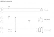
1) The 120µF capacitor appears to be in series with the mid-range driver. The mid-range driver already has a 60µF capacitor in series. I would think the 120µF capacitor would be serving as a high-pass filter for the woofers.
2) The 2.65mH air-core inductor, which appears to be in series with the woofers, is on the negative line (on the wire returning from the negative terminal of the woofer to the negative terminal of the binding post). All the crossover schematics I have seen show the components on the positive lines. (The inductor in my speaker measures 2.65mH, although the engineering drawing specifies 2.623mH).
I understand that these questions may only be serving to show my ignorance in this subject. As can be seen in the engineering drawing, the wires to the negative terminals of the woofers, the wire to the positive terminal of the mid-range, the air-core inductor, and the 120µF capacitor all connect to one solder point. Why is this, and how is it correctly drawn?
I also have some notes from the marketing literature about the AR93s speakers, which describe the crossover design. Perhaps they can help shed light on this crossover.
I have a pair of AR93s speakers that I am restoring. I have refoamed the woofers and mid-range drivers, and am now working on the crossovers. I want to draw up a schematic of the crossover, and would like help making sure that it is drawn correctly. I am a complete beginner at drawing schematics, and I am unfamiliar with the basics of electricity flow in a circuit. I could find no schematics for the AR93s crossover on the internet, and would like to make a good one to share.
I have examined the actual crossover taken from the speaker, and have drawn up a schematic that shows the connections pretty accurately. I also found a great engineering drawing of the crossover from the library at the Classic Speaker Pages. This drawing appears to be authentic, from Acoustic Research, and exactly matches the crossover from my speaker. This drawing, and many others for AR speakers, can be found here:
http://www.classicspeakerpages.net/...special_sections/drawings/SpeakerDrawings.swf
I am a bit puzzled by this crossover, for a couple reasons:
1) The 120µF capacitor appears to be in series with the mid-range driver. The mid-range driver already has a 60µF capacitor in series. I would think the 120µF capacitor would be serving as a high-pass filter for the woofers.
2) The 2.65mH air-core inductor, which appears to be in series with the woofers, is on the negative line (on the wire returning from the negative terminal of the woofer to the negative terminal of the binding post). All the crossover schematics I have seen show the components on the positive lines. (The inductor in my speaker measures 2.65mH, although the engineering drawing specifies 2.623mH).
I understand that these questions may only be serving to show my ignorance in this subject. As can be seen in the engineering drawing, the wires to the negative terminals of the woofers, the wire to the positive terminal of the mid-range, the air-core inductor, and the 120µF capacitor all connect to one solder point. Why is this, and how is it correctly drawn?
I also have some notes from the marketing literature about the AR93s speakers, which describe the crossover design. Perhaps they can help shed light on this crossover.
- Combination series and parallel network
- Series feeds woofers, then crosses over to the mid-range
- Parallel feeds tweeters
- Woofers and mid-range have 12dB/octave slopes
- Mid-range has 12dB/octave mechanical crossover for the high end
- Tweeter uses a 1st order electrical network, plus mechanical slope, for a total of 18dB/octave slope
- Crossover frequencies 350Hz, 2000Hz
Attachments
I'd like to see some photos of this Acoustic Research AR-93S speaker. It's different, and I don't find much info on it! 
It IS all a bit of a head-scratcher, but if you swap it all around, it looks like a conventional sort of series crossover on the bass and mid units. Phase between the bass and mid (dome?) is a bit ropey, but the tweeter is well aligned with the mid so it all works rather well. Impedance hovers around 4 ohms throughout.
It IS all a bit of a head-scratcher, but if you swap it all around, it looks like a conventional sort of series crossover on the bass and mid units. Phase between the bass and mid (dome?) is a bit ropey, but the tweeter is well aligned with the mid so it all works rather well. Impedance hovers around 4 ohms throughout.
Attachments
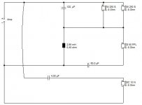
Thank you for your nice schematic, Steve! What do the notations next to the drivers mean (e.g. G 50 FFL)? I'll take some photos of the AR93s speakers soon, and post them.
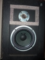
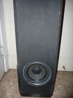
The mid-range is actually an 8" paper cone very similar to the woofers (the woofers and mid-ranges all used the same size replacement foam surrounds). The mid-ranges originally had a thick, flat paper or felt dust cover. I replaced them with a domed felt dust cover while refoaming, but now, having read that the mid-ranges use a "mechanical crossover" as the low-pass filter, I wonder if the dust caps were an important part of that. Since I still have them, I may put them back on. Also, both the woofers and the mid-ranges had a ring of thick, rubbery glue applied over the inside circumference of the foam surrounds. Last, but not least, the woofers and mid-ranges all have a length of thick lead wire glued right into the joint between the cone apex and the voice coil former. This makes me think that Acoustic Research fiddled with the drivers to make them sound just right.
The tweeters are also paper cones, 1 1/2" diameter, in a bulls-eye shape. On my tweeters, the circular metal face around the tweeter cone is unfinished, and has a fine white corrosion dust covering it. I think that means it is aluminum.
I completely ripped out the crossovers, because they use the cheap spring-terminal type of connectors. I will replace those with gold-plated, five-way binding posts.
Photos to follow.
The notations on the drivers are simply the Visaton equivalents I used to model the crossover, since I enjoy that sort of stuff, and find Acoustic Research designs endlessly fascinating.
AR design was led by Edgar Villchur, who tended to modify drivers and cabinets to work on simple crossovers. AR would often add mass to cones, sponge damping around dustcaps or even use metal mesh dustcaps. Evidently they modified surrounds for what they wanted too. AR cone tweeters were interesting too, being able to crossover quite low.
Bottom line was AR used acoustic suspension to the max, which is where the air in the cabinet does way more than the surround to control the excursion. This relies on heavy cones, strong magnets and heavy wadding in relatively small boxes for low distortion and copious bass. Generally quite inefficient electrically. Anecdotally they work best with transistor amps.
What is interesting about AR drivers is they mechanically filter and rolloff in a way that we do electrically through the crossover these days. I believe Edgar was a complete genius, optimising technology that seems primitive to our modern viewpoint.
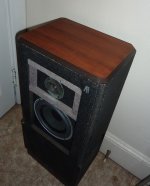
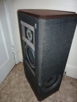
Here are some photos of one AR93s speaker, with the cloth sock off. There are two woofers, one on each side of the cabinet. I have more photos (including close-ups of the drivers), and can post them, if requested.
Attachments
Apologies for the light threadjacking but I'm working on my own pair of AR93s speakers and was hoping for input from a couple of other owners.
Do you guys have any sealing material/gasket between the rim of the drivers and the speaker enclosure? I just took apart one of the speakers to replace a failed tweeter and noticed that I don't have any sealing material behind the drivers.
I had my speakers re-foamed by a shop ≈10 years ago so I don't know what was there originally. I had thought that AR was big on sealing their enclosures...
Thanks all!
I am a bit puzzled by this crossover, for a couple reasons:
1) The 120µF capacitor appears to be in series with the mid-range driver.
The mid-range driver already has a 60µF capacitor in series. I would think
the 120µF capacitor would be serving as a high-pass filter for the woofers.
Hi,
The 120uF effectively isn't in series with the mid, such is the nature of
series crossovers, which can be very confusing. The bass/mid x/o is
series first order on the bass and second order on the midrange.
More confusing is the current through the mid mostly passes through
the 120uF so it seems to be in series, but it strictly it isn't. One way
of looking at it is the mid is driven by the voltage across the inductor
with current provided by the capacitor, and the bass units are driven
by the voltage across the capacitor with the inductor providing current.
Best to look at as a 1st order series driving a bass unit and a mid unit
fitted with a series capacitor (the 60uF). Unlike parallel the impedance
of one drive unit (or unit +cap) affects the signal to the other driver.
(And hence the possible superiority of 1st order series vs. parallel,
you can use this interaction to your advantage if it works well.)
rgds, sreten.
two different schematics above
bandolino's schematic shows a Third Order high-pass filter to the midrange , and a Second Order low-pass filter to the woofer
-{which combines with the mechanical upper midrange rolloff of the woofer to form a higher order low pass filter}.
The position of the 60uF cap is unusual.
Depending on the output impedance of the driving amplifier , it could be argued that the mids' high-pass filter is Second Order electrical ,
and there will also be the mechanical roll-off of the low frequency end of the mids driver combined with the electrical network to form a higher order high-pass filter.
The inductor is connected in such way so as to cause it to perform two functions - one for mids and other for bass.
Yes, I do see an argument for First Order low-pass to the woofer , but it would only be partially such.
I think there will be a bit of a mixture occurring there ,
and what will actually be happening will depend on the inductances of the voice-coils of woofers and midrange.
Last edited:
bandolino's schematic shows a Third Order high-pass filter to the midrange , and a Second Order low-pass
filter to the woofer . The position of the 60uF cap is unusual. Depending on the output impedance of the
driving amplifier , it could be argued that the mids' high-pass filter is Second Order electrical , The
inductor is connected in such way so as to cause it to perform two functions - one for each driver.
system7 has drawn a different circuit.
Hi, Every point above in your post is wrong, rgds, sreten.
Last edited:
corrections were made in my post above
Hi sreten ,
I realized my errors and was editing whilst you posted.
What remains in my post is defendable - it requires some thinking about ,
and in particular about the inductances along with the effective increases of resistance with frequency in the woofers and midrange driver.
Villchur and who-ever other engineers there knew how to integrate external crossover components with the electrical and mechanical characteristics of their drivers.
Further discussion is welcome !
Last edited:
The best source of information for Acoustic Research loudspeakers is :Apologies for the light threadjacking but I'm working on my own pair of AR93s speakers and was hoping for input from a couple of other owners.
Do you guys have any sealing material/gasket between the rim of the drivers and the speaker enclosure? I just took apart one of the speakers to replace a failed tweeter and noticed that I don't have any sealing material behind the drivers.
I had my speakers re-foamed by a shop ≈10 years ago so I don't know what was there originally. I had thought that AR was big on sealing their enclosures...
Thanks all!
Home Page | The Classic Speaker Pages
Some sort of roofing tar material was and still is used to glue and seal speakers in place. A cheap solution, and NOT convenient for frequent rebuilds. I don't know the brand name used, but it melts at quite low temperature.
These days a lot of firms use a soft plastic gasket to seal against air leaks. Quite important with closed box. Air leaks produce a curious shudder on bass cones, but there are a variety of plumbing materials or cardboard that would do the job quite adequately IMO. I increasingly get rubbery stuff from builders merchants.
FWIW, the schematic I came up with was simply untangling the confusing AR filter schematic. AFAIK, it is an accurate electrical representation of the crossover in a form the modern eye can follow. Just Topology really.
- Status
- This old topic is closed. If you want to reopen this topic, contact a moderator using the "Report Post" button.
- Home
- Loudspeakers
- Multi-Way
- Acoustic Research AR93s crossover: is this schematic correct?