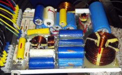
I am working on rebuilding the crossovers in my Duntech Crown Prince speakers. After speaking with Duntech AU they suggested replacing all the capacitors and resistors as Technology in the last 20 years has greatly improved these parts. So I have torn one crossover apart and mapped out the schematic and verified all the parts values with the exception of the Inductors which i will have measured next week.
There are many interesting things and some puzzling things as well about this crossover design. I will start with the top working down on the schematic.
There are many interesting things and some puzzling things as well about this crossover design. I will start with the top working down on the schematic.
Attachments
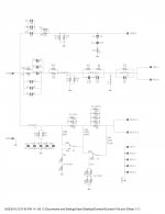
The first thing I noticed is the upside down Zobel network forming more of a Boucherot cell in the tweeter network. As expected a 6db per octave first order network as i have always read Dunlavy used.
The midrange gets quite interesting. I have read that each speaker was "voiced" to fit within a chosen frequency response window. I was a little concerned that the left and right speakers would be different. But both crossovers check out to have all the same values...BUT the resistors while the same value, differ in construction! there are 3 distinct types (and colors) of resistors used and they are not the same parts in the same places. again they are the same values however!
Interesting in the midrange section is the zobel across the high pass caps. I checked this many times to make sure that this is in fact exactly how it is wired and it is!
The group of caps totaling 45uf at the input to the midrange section and Inductor L4 is expected to form a 6db first order network. But L2 in the middle of the voltage divider was not. I'm curious about that. L4 is followed by two Tank circuits where they must be tuning out some peaks in the response at a guess??
Where things get interesting is C4. this is a 50uf single very large cap. Everywhere else in the circuit he used multiple paralleled caps to form a larger value. why in this location only did he choose to use one single large cap?
Moving down to the woofer network see L10 (typo, was supposed to be L1) which is a very large inductor. followed by a Zobel network with multiple paralleled caps made of 10, 10, 10, 20, 20uf caps which seems odd to me that they didn't use 20, 20, 20, 10 instead? and again why did he use one large 50uf cap in the midrange tank circuit and not kept form by using 20, 20, 10uf as elsewhere? maybe i am making more of this then there really is but it is interesting.
The following resistor switch network is a low frequency room compensation network that was done away with in later versions. as suggested I will be removing this network as well.
I would really like to know what the mids are but I am just not going to tear the cabinets apart to find out. the woofers are being re-foamed right now so I had to take them out and I can see the back of the tweeter from the inside of the crossover cavity.
To me the speakers sound just slightly recessed in the midrange. like vocals are slightly further back in the hall then I am used to hearing from my Hales Revelation 3 speakers I upgraded from. Also the Duntechs just don;t have the same transient response the Hales have! which to me is my number 1 pet peeve about loudspeakers. I mean if you stand next to a guy banging on a snare drum, the sound is very very sharp and it makes you jump/flinch. same with a triangle. the sound while soft has very large transients that when played back on 99% of the speakers I have ever hear, just round everything off into mush. The Hales were very very good at that. the best i ever heard in fact. where as the Duntechs are very soft sounding...
I am hoping that rebuilding the crossovers will open the soundstage up a bit and maybe bring that midrange forward. according to Duntech AU new caps and resistors really bring these speakers alive...so we will see.
Oh yeah BTW, the recessed Midrange MIGHT have been from a resistor that wasn't soldered!!! One one crossover board in the midrange section at the input, there are two paralleled resistors. one wasn't soldered to the other on either end. it was just wrapped around loosely! and the glaze they dipped the board in was holding it in place!! ooops! a factory mistake!!!
Last edited:
Frequency response and peaks therein can often have the effect of making a given speaker sound "fast"... in theory the Duntechs have nearly ideal transient response, which is why they can do a 1kHz. square wave more or less correctly... or at least that is what some of his speakers did, not sure about this model.
Also, just a thought, depending on the vintage, later on John Dunlavy was having some troubles with the business, so he/they may have put speakers together with whatever they had on hand to do the job, as in the differences in the xovers - or perhaps you have two different production runs for the xovers and/or the cabinets? Only speculation.
I kinda doubt the resistors will have much effect unless perhaps if you switch to thick film types. The caps are more likely to have an effect, imo...
_-_-bear
Changing out those sand cast resistors to wire wound will make a difference, we fond goop degrades the sound (dead) this maybe the biggest issue in my books when redoing that xover.
Also your Hales have better bass than the Duntechs , this goes along way in dynamic reproduction and pretty much a weak spot in all of Dunleavy's speakers IMO, aside he was pretty crafty and creative ...
Also your Hales have better bass than the Duntechs , this goes along way in dynamic reproduction and pretty much a weak spot in all of Dunleavy's speakers IMO, aside he was pretty crafty and creative ...
Last edited:
Changing out those sand cast resistors to wire wound will make a difference, we fond goop degrades the sound (dead) this maybe the biggest issue in my books when redoing that xover.
Also your Hales have better bass than the Duntechs , this goes along way in dynamic reproduction and pretty much a weak spot in all of Dunleavy's speakers IMO, aside he was pretty crafty and creative ...
This is really interesting me now. I visited a famous mastering studio last month and took my usual demo material. I felt that the presentation was rather soft on the top end and very compressed sounding for such a large system. It was Dunlavy SC-V's and SC-IVs in a 5.1 set-up. I'm wondering if those crossovers are chock full of electrolytic caps too. Performance was poor enough that I wondered if he had a compressor mistakenly plugged in the monitoring chain somewhere. I really struggled to find something complimentary to say after the visit.
Greg
My new Agilent LCR meter arrived last night and i was able to measure the inductors and do some math. the main woofer Inductor is 1.5mh which should put the crossover point around 425hz.
L2 in the midrange I measured .120mH which interestingly enough corresponds to the 120 printed on it! at a guess this should put the crossover point to the tweeter around 5700hz??
The first tank circuit I measured .15mH which corresponds to the 147 printed on it. which according to an online LC tank calc. make this a 10.6khz filter with a Q= .18 and a Z= 1.82ohms. SO maybe a notch filter?
The Inductor to ground I measure 5.95mH so I'm guessing this is a 6mh inductor.
The last tank circuit I measure 0.045mH which corresponds to the 46 printed on the side which makes this a 3.355khz filter with a Q= .43 and a Z= .4ohms
Interesting stuff!! the 16.05uF for the tweeter seems very very low crossover point?
and when replacing these inductors. I wonder how accurate i need to be? IF for example the 147 printed on the side of L3 really means .147mH is .15mH close enough? Can a .003mH difference really be much in the terms of frequency??
I'm hoping that my measurements of these inductors are accurate enough.
Changing out those sand cast resistors to wire wound will make a difference, we fond goop degrades the sound (dead) this maybe the biggest issue in my books when redoing that xover.
I am replacing the resistors with Mundorf Metal Oxide resistors! and I am working on a special deal on some caps. will see if I can make it happen. But speaking of goop....
I have been considering what to use for circuit board material and for board damping if any? I had considered something like Greenglue under the inductors and caps with zip ties to hold them to the board. Or some sort of mounting with thin sorbothane sheets sandwiched between the parts or something.
I want to raise the resistors up off the board slightly so I will probably use pins or turrets or something on the resistor leads as standoffs but really don't like using component leads as a mounting method. I had considered 1 small dab of silicone under each resistor end...but im still thinking about it.
Zc
That explains it .
The D28AF is actually 6 ohms, and the shunt R reduces the resistance seen by the cap to about 4 ohms.
http://www.gattiweb.com/images/dynaudio/d28af_data.pdf
The D28AF is actually 6 ohms, and the shunt R reduces the resistance seen by the cap to about 4 ohms.
http://www.gattiweb.com/images/dynaudio/d28af_data.pdf
FWIW, I have recently listened extensively to the Duntech sovereighn
SOVEREIGN
(I think it's the succesor of Dunlavy/same company) in a well treated mastering studio, driver by Hypex ncore 1200 Watt modules (prototypes). It was an amazing experience. Yes, the vertical sweetspot is very narrow and the large signal dynamics are not as good as with good horn speakers, but the micro detail is very, very good.
The best thing (and for me personally my reference from now on on this subject) was the stereo imaging and especially the mono. While listening to Roger Waters' "Amused to death"(one of the best produced albums ever with great qsound effects),I checked three (3!) times to check if the center speaker was really not playing (It was a 5.1 setup but I listened only stereo).
I am sure that part of the experience was created by using the ncore amps, which are by far the best amps I have heard so far, but the linear phase response of the speaker also made a very large contribution.
I am convinced that linear phase is essential for true reproduction. This can either be achieved by using acoustically 1st order slopes as dunlay and others, or use 24dB LR xover with time reversed allpass filter to correct the phase as Grimm audio and other do.
I know that the phase audibility is a much debated issue, but I personally score 100% on any blind abx test I have done so far (quite a couple), for me it doesn't matter on which frequency it happens be it 50Hz or 10kHz.
I have to admit that I am a trained, experienced audio professional and I have done all the tests with my own soundcheck tracks, but these are all just music and no specific test signals.
I think that anyone can learn to hear these differences, one just has to know what to hear. But that basically is true for everything in listening to audio.
sorry if I went a bit ot, just my 2cts
Kessito
- Status
- This old topic is closed. If you want to reopen this topic, contact a moderator using the "Report Post" button.
- Home
- Loudspeakers
- Multi-Way
- Understanding John Dunlavy's Crossover Designs Crown Prince