Something is wrong with the tweeter circuit. Assuming the woofer and tweeter circuits are running in parallel, the tweeter circuit is going to short out at low frequencies and fry your amp. You need a series cap before the shunt inductor. Maybe the caps you have after the inductor are before it.
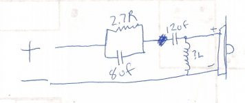
AHHHH I see, How about this?
That looks reasonable for a 2nd order electrical with a response shaping component pair added.
I think you'll find it's 2R7, then 8µF, then the parallel inductor, then the 12µF. So your bass is 2nd order and the tweeter 3rd order.
That could be as well...
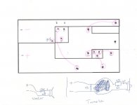
In the diagram with the square blocks the lines represent the poles of the existing crossover components from the factory and the blocks represent the traces on the crossover PCB as it exists now.
TR & TC8 are in parallel to each other then connected in series to the right end of TC12.
At the junction of TC12 to T+ the one end of the parallel TI comes in.
It looked to me that TI has only a junction to the side of TC12 that is connected to T+.
TR & TC8 are in parallel to each other then connected in series to the right end of TC12.
At the junction of TC12 to T+ the one end of the parallel TI comes in.
It looked to me that TI has only a junction to the side of TC12 that is connected to T+.
- Status
- This old topic is closed. If you want to reopen this topic, contact a moderator using the "Report Post" button.
- Home
- Loudspeakers
- Multi-Way
- Crossover Layout