I'm interested in building a slim floor-standing column speaker using either a tapered TL or an MLTL configuration. After carrying out a few simulations using the MJK worksheets, I found that for a given driver, the response of the two types is quite similar. The main differences are that the TL has a small amount (~2dB pk-pk) of ripple between 100Hz and 1kHz when using a 5:1 line taper, whereas the MLTL has much higher port velocity (about 5 times higher).
Are there any benefits in terms of sound quality for one type of cabinet versus the other ? The TL needs a slightly bigger cabinet, maybe +5% in each dimension.
Out of interest, I also put the 'coupling chamber + line' configuration, as used in IPL Acoustic's TL designs, into the MJK worksheet, and this gave a terrible response however much I fiddled with the line damping.
I've modeled many, many TLs and built quite a few for personal use. The main advantage of a tapered TL is its lower terminus air velocity, and the main advantages of an ML-TL are it's simpler to build and will have a smaller volume for the same F3. What I've found is that is takes 20-25% more volume in a tapered TL to achieve the same F3 as in a truly equivalent ML-TL.
The higher port air velocity in an ML-TL isn't necessarily a "show stopper". If you can keep its peak velocity to no more than 3%-5% of the speed of sound with an input power to the driver that causes it to reach Xmax+15%, while the system output SPL reaches whatever you want it to, the audible results should be satisfactory. You also need to pay attention to the frequency at which the port air velocity peaks; if it occurs at 40 Hz it will be more likely to be excited and audible than if at 20 Hz, for instance, just due to musical content considerations. This is just one of the compromises one has to deal with.
But, to answer your main question if the two types of TL designs are as similar as you've described, there will be no audible differences in their sound, at least IMO and from my experience.
Paul
I'm interested in building a slim floor-standing column speaker using either a tapered TL or an MLTL configuration. After carrying out a few simulations using the MJK worksheets, I found that for a given driver, the response of the two types is quite similar. The main differences are that the TL has a small amount (~2dB pk-pk) of ripple between 100Hz and 1kHz when using a 5:1 line taper, whereas the MLTL has much higher port velocity (about 5 times higher).
Are there any benefits in terms of sound quality for one type of cabinet versus the other ? The TL needs a slightly bigger cabinet, maybe +5% in each dimension.
Out of interest, I also put the 'coupling chamber + line' configuration, as used in IPL Acoustic's TL designs, into the MJK worksheet, and this gave a terrible response however much I fiddled with the line damping.
Paul,
Thanks for the info.
The MJK worksheets indicate that the MLTL peak port velocity is indeed at around 40Hz, and at the driver Xmax it will be reaching about 7% of the speed of sound.
The cabinet dimensions are coming out at 19 x 24 x 90cm for the MLTL and 21 x 31 x 95cm for the TL, so there isn't a huge size penalty.
Regards,
Chris.
Chris, you didn't mention what size of port tube you modeled. Can you increase its diameter to lower the air velocity (meaning, of course, its length will need to be increased, also, to maintain the system tuning frequency)? If you did that and were also able/willing to tune the system a bit lower, you could move the peak down in frequency some. One more thing, you are aware that the Y-axis on the air velocity graph has units of mm RMS? If you're using the driver's Xmax in mm Peak directly on the graph, instead of converting to mm RMS by multiplying the rated Xmax by 0.707, you're actually pushing the driver to 41.4% over its rated Xmax (just a thought).
Paul
Paul
Paul,
Thanks for the info.
The MJK worksheets indicate that the MLTL peak port velocity is indeed at around 40Hz, and at the driver Xmax it will be reaching about 7% of the speed of sound.
The cabinet dimensions are coming out at 19 x 24 x 90cm for the MLTL and 21 x 31 x 95cm for the TL, so there isn't a huge size penalty.
Regards,
Chris.
Chris, you didn't mention what size of port tube you modeled. Can you increase its diameter to lower the air velocity (meaning, of course, its length will need to be increased, also, to maintain the system tuning frequency)? If you did that and were also able/willing to tune the system a bit lower, you could move the peak down in frequency some. One more thing, you are aware that the Y-axis on the air velocity graph has units of mm RMS? If you're using the driver's Xmax in mm Peak directly on the graph, instead of converting to mm RMS by multiplying the rated Xmax by 0.707, you're actually pushing the driver to 41.4% over its rated Xmax (just a thought).
Paul
Paul,
My MLTL simulation used a port dia of 5.5cm and length of 13cm. This just happened to be a readily available port with a flared flange, which tuned correctly. However, I could use a bigger dia (and longer) port as you suggest, although the pipe resonance in the port itself might then be noticeable.
Well spotted on the cone displacement plot. I must admit I did not notice that it was rms displacement !
The port velocity in my worksheet (an old version from 2006) is scaled in velocity relative to the speed of sound.
Chris.
Chris,
Okay, a couple more comments. Martin's software is only valid for a non-flared port, which means that whatever length you modeled will need to be increased for the flared port in order to achieve the desired tuning frequency. Typically increasing the modeled length by 1/2" for each flared end will do the trick, but that's not a guarantee. Yes, if you use a larger diameter port that also has a longer length, a pipe resonance might rear its ugly head, but you can usually mitigate that effect at least partially if not completely by moving the port's location a bit which forces that resonance higher up in frequency and possibly better attenuated by the crossover. The graph for air velocity has always been scaled to a percentage of the speed of sound AFAIK and still is for later versions of Martin's software. So, a peak velocity of 3% of the SOS is equal to ~10 m/s, and at 5% of the SOS, it's ~17 m/s.
When I test a model to see what happens to the port/terminus air velocity, I increase the Reference input power (with Rref set to the actual nominal impedance of the driver as seen on the impedance graph) until the driver's excursion hits Xmax+15%, in RMS units, of course. For any specific air velocity magnitude, the lower in frequency of its peak, the better, and the lower in frequency where the driver hits Xmax+15%, also the better.
Paul
Paul,
My MLTL simulation used a port dia of 5.5cm and length of 13cm. This just happened to be a readily available port with a flared flange, which tuned correctly. However, I could use a bigger dia (and longer) port as you suggest, although the pipe resonance in the port itself might then be noticeable.
Well spotted on the cone displacement plot. I must admit I did not notice that it was rms displacement !
The port velocity in my worksheet (an old version from 2006) is scaled in velocity relative to the speed of sound.
Chris.
Paul,
Thanks for the additional comments.
I guess these potential port velocity issues tend to favour the TL. My offset tapered TL worksheet predicts a port velocity of 0.002*c at the default 1W input power, so even at 100W input, it is still going to be below the recommended 0.03*c
Chris.
Thanks for the additional comments.
I guess these potential port velocity issues tend to favour the TL. My offset tapered TL worksheet predicts a port velocity of 0.002*c at the default 1W input power, so even at 100W input, it is still going to be below the recommended 0.03*c
Chris.
Yep, that's a big advantage of a tapered TL. I've built several tapered TLs for personal use, but a few more ML-TLs for their advantages. If I'm really trying to minimize overall size, I'm willing to live with the higher port air velocity of an ML-TL as long as it doesn't appear there will be objectionable port noise. Sometimes, too, a particular driver just doesn't perform as good as one wants in a tapered TL. All speaker designs have compromises unfortunately.
Paul
Paul
Paul,
Thanks for the additional comments.
I guess these potential port velocity issues tend to favour the TL. My offset tapered TL worksheet predicts a port velocity of 0.002*c at the default 1W input power, so even at 100W input, it is still going to be below the recommended 0.03*c
Chris.
Hi,
One thing you can do with a MLTL you can't with a TL is tinker with the tuning.
Sometimes for vented boxes in some rooms lower tuning simply works better.
rgds, sreten.
FWIW MJK reports he has modeled Fried type TL cabinets and found they
simply don't work as described or very well given the total box volume.
After carrying out a few simulations using the MJK worksheets, I found that for a given driver, the response of the two types is quite similar.
Hmm? While ther are different ways to tune, as far as I can tell a Tapered TL should have an almost entirely damped lower impedance peak:
An externally hosted image should be here but it was not working when we last tested it.
resulting in a shallow knee response profile like this:
An externally hosted image should be here but it was not working when we last tested it.
An ML-TL will have a dual impedance peak

resulting in a more efficient, but sharper knee response profile like this:

The different between the two alignments results in a different amount of overlap between the terminus' and driver. The Tapered TL will have an excursion profile like this, where the line controls the driver lower in frequency:
An externally hosted image should be here but it was not working when we last tested it.
while the ML-TL will have an excursion profile like this, where the port starts to act against the driver:
An externally hosted image should be here but it was not working when we last tested it.
While I don't want to make claims of what's "right" and "wrong", i think that if the tapered TL (quarter wave) is getting the same response profile as the ML-TL (bass reflex) then you're probably modelling the Tapered TL... unusually.
Last edited:
If a tapered TL has a single impedance peak like you illustrated, it's had the life literally stuffed out of it with the result of absolutely no contribution from the terminus' output to the bass response. If you're going to do that, you might as well just make a big sealed box rather than wasting your time building a complex tapered line.
Paul
Paul
Hmm? While ther are different ways to tune, as far as I can tell a Tapered TL should have an almost entirely damped lower impedance peak:
An externally hosted image should be here but it was not working when we last tested it.
resulting in a shallow knee response profile like this:
An externally hosted image should be here but it was not working when we last tested it.
An ML-TL will have a dual impedance peak
resulting in a more efficient, but sharper knee response profile like this:
The different between the two alignments results in a different amount of overlap between the terminus' and driver. The Tapered TL will have an excursion profile like this, where the line controls the driver lower in frequency:
An externally hosted image should be here but it was not working when we last tested it.
while the ML-TL will have an excursion profile like this, where the port starts to act against the driver:
An externally hosted image should be here but it was not working when we last tested it.
While I don't want to make claims of what's "right" and "wrong", i think that if the tapered TL (quarter wave) is getting the same response profile as the ML-TL (bass reflex) then you're probably modelling the Tapered TL... unusually.
If a tapered TL has a single impedance peak like you illustrated, it's had the life literally stuffed out of it with the result of absolutely no contribution from the terminus' output to the bass response.
the model still shows 3db of lift over a wide bandwidth. The F3 compared to a sealed box of the same size goes from 90hz to 52hz, and the F10 also drops slightly from ~33hz to ~30hz. The stuffed line still shows reduced excursion near its tuning.
Beyond that, the more shallow rolloff can sound better in some rooms and placements vs a flat ML-TL, due to room modes and pressure vessel gain causing peaking in the 20hz to 50hz region, which is a big factor in slow perceived bass.
If you ask me, bothering with any kind of resonator - line or port or passive radiator - is a waste of time. Use 3 or 4 carefully placed, small, equalized multiple sealed 15" subs for accurate bass in real rooms below 100hz. Go dipole or cardioid above 100hz.
Last edited:
Hmm? While ther are different ways to tune, as far as I can tell a Tapered
TL should have an almost entirely damped lower impedance peak:
Hi,
No it doesn't. It has the same double peaks at lower stuffing densities.
It has to have double peaks for the line output to be significantly useful.
rgds, sreten.
I must give credits to Paul ( thanks ") ) for having inspired me to build
) for having inspired me to build
my first tapered TL . It was a lot of work , about two years ago , and the speakers are still in my room , so it mustn't be that bad
I didn't put any stuffing inside
but much use of constrained layers damping ...and when I found a pair
of rotten Altec Mod.300 and repaired the foam , those gray woofers
really match the vinyl gray finish I adopted
Tony
) for having inspired me to buildmy first tapered TL . It was a lot of work , about two years ago , and the speakers are still in my room , so it mustn't be that bad
I didn't put any stuffing inside
but much use of constrained layers damping ...and when I found a pair
of rotten Altec Mod.300 and repaired the foam , those gray woofers
really match the vinyl gray finish I adopted
Tony
While I don't want to make claims of what's "right" and "wrong", i think that if the tapered TL (quarter wave) is getting the same response profile as the ML-TL (bass reflex) then you're probably modelling the Tapered TL... unusually.
Hi,
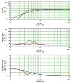
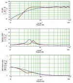
In my modelling, the MLTL was uniformly stuffed at 0.5 lb/cu ft, but the TL was only stuffed in the first half (from driver end) of the line at 1 lb/cu ft. The second half of the TL was left empty. I used a 5:1 taper, starting at 3.4*Sd and ending at 0.68*Sd. The driver was a 6.5" poly-coned unit from HiVi, although that may not be my final choice.
The attached plots show freq resp, impedance and cone excursion for each configuration. If I stuffed the whole of the TL, then the plots were very similar to yours, with very little bass reinforcement.
Chris.
Attachments
What I've found to be almost always the best stuffing configuration for the best overall system response coupled with optimum port/terminus air velocities and driver excursion considerations, is this: In an ML-TL only the first 50% of the line's length contains stuffing, while in a tapered TL it's typically the first 60-67% that's stuffed. If stuffing is added beyond those lengths, the detriment to F3 is usually too severe for whatever is gained anywhere else. Increasing the stuffing density, however, for the lengths I mentioned will provide improvements in response smoothness with a much smaller detriment to F3. Just a whiff of stuffing in the terminus of a tapered TL will completely kill its output. In a tapered TL I will use a larger taper ratio before increasing stuffing density or length because the larger taper also minimizes response ripples (I never use a taper ratio smaller than 10:1).
Paul
Paul
Hi,
In my modelling, the MLTL was uniformly stuffed at 0.5 lb/cu ft, but the TL was only stuffed in the first half (from driver end) of the line at 1 lb/cu ft. The second half of the TL was left empty. I used a 5:1 taper, starting at 3.4*Sd and ending at 0.68*Sd. The driver was a 6.5" poly-coned unit from HiVi, although that may not be my final choice.
The attached plots show freq resp, impedance and cone excursion for each configuration. If I stuffed the whole of the TL, then the plots were very similar to yours, with very little bass reinforcement.
Chris.
I agree with you on one point; I would never recommend a TL of any kind for strictly subwoofer use, which is what you're really talking about in your last statement. It's a waste of time, but if someone wants to, that's fine. But since I don't use, want or need a subwoofer, all of my designs are for full-range systems, usually 3-ways. A TL is inherently a 4th-order system and its response shape can be tailored to have 4th-, 3rd- and 2nd-order rolloffs below F3, with obviously different effects on its impedance profile and how much bass contribution is provided by the port or terminus. Since there is very little, if any, content in most music (excluding special effects for movies, for instance) below 30 Hz, much less at 20 Hz, I consider it waste of abilities to force a 2nd-order rolloff because the improvement provided below 30 Hz is wasted, while at the same time, there is less output above 30 Hz where there is actual content to be heard.
Paul
Paul
the model still shows 3db of lift over a wide bandwidth. The F3 compared to a sealed box of the same size goes from 90hz to 52hz, and the F10 also drops slightly from ~33hz to ~30hz. The stuffed line still shows reduced excursion near its tuning.
Beyond that, the more shallow rolloff can sound better in some rooms and placements vs a flat ML-TL, due to room modes and pressure vessel gain causing peaking in the 20hz to 50hz region, which is a big factor in slow perceived bass.
If you ask me, bothering with any kind of resonator - line or port or passive radiator - is a waste of time. Use 3 or 4 carefully placed, small, equalized multiple sealed 15" subs for accurate bass in real rooms below 100hz. Go dipole or cardioid above 100hz.
interesting. I always wondered what was the difference between a MLTL and pipe shaped Reflex....Im hesitant to say there isnt one, since Im no expert, but It makes me wonder...
How many of those 80's/90's 'tower reflexes' actually stumbled upon MLTL operation.
I used a taper ratio of 20:1 on the basis that in a reflex system the 'rule of thumb' i know is a min vent area of 1/7th Sd, which is what I have used in several reflex designs (eg 5" woofer, 2" ID vent).
How many of those 80's/90's 'tower reflexes' actually stumbled upon MLTL operation.
I used a taper ratio of 20:1 on the basis that in a reflex system the 'rule of thumb' i know is a min vent area of 1/7th Sd, which is what I have used in several reflex designs (eg 5" woofer, 2" ID vent).
Last edited:
I'm sure there have been a lot of accidental ML-TLs created over the years, and I'm just as sure most of them will be quite a bit removed from having an optimal performance that can be achieved by proper location of the port. I've used taper ratios from 10:1 to 26:1 with good success.
Paul
Paul
interesting. I always wondered what was the difference between a MLTL and pipe shaped Reflex....Im hesitant to say there isnt one, since Im no expert, but It makes me wonder...
How many of those 80's/90's 'tower reflexes' actually stumbled upon MLTL operation.
I used a taper ratio of 20:1 on the basis that in a reflex system the 'rule of thumb' i know is a min vent area of 1/7th Sd, which is what I have used in several reflex designs (eg 5" woofer, 2" ID vent).
- Status
- This old topic is closed. If you want to reopen this topic, contact a moderator using the "Report Post" button.
- Home
- Loudspeakers
- Multi-Way
- Tapered TL vs MLTL