Greetings all,
this is my first attempt at designing a sealed enclosure for Altec 515B. I have done some search and the overall conclusion was that "no bass can be obtained" from the driver.
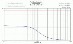
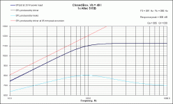
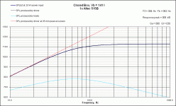
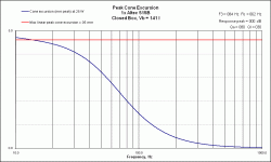
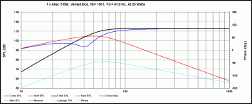
Based on attached model from Unibox, I am confused by the statement, because according to the model, at the design frequency of 40 Hz, the woofer can be equalized to 100dB, without exceeding the Xmax. Thus the overall response is still 100dB.
The parameters used were:
Fs 24.30 Hz
Re 12.00 Ohm
Qms 6.62
Qes 0.23
Sd 890.0 cm2
Vas 757.0 l
Xmax peak 4.60 mm
(Le) 0.01 mH
(Le2) 0.00 mH
(Re2) 0.00 Ohm
Nominal Power 25.0 W
If there is any better sealed alignment, please let me know.
What am I missing?
Kindest regards,
M
Attachments
You aren't missing anything and your simulaion looks correct. A little mental math would confirm: in a sealed box fs and Qt track for resonance frequency changes. That is the ratio of fs to Qt is fixed. If you start with a Qt of about 0.2 (a little less than Qes) you want to raise it to 3 or 3.5 times that. That would require a box that shifts resonance from 24 to the 75 to 90, as you have done. No more variables to play with, so that is about the only allignment available.
The "no bass" comment comes from the 3dB down at 90, simulated response that you see. The woofer was designed for high efficiency and possible horn loading, so it not a natural subwoofer. If you want to go the EQ route, that will be fine, assuming you have the excursion to get the output you need.
David S.
I figured when I read this earlier that the idea was that 100db was enough for the OP and that with the 25W posted, that corresponded to around 45 Hz.
If the speaker was eq'ed down above 45Hz (as opposed to being boosted at low frequencies) to be flat from about 45Hz up then the -10db point would be around 25Hz. Whether that can be achieved however I'm not certain.
That should result in something that can produce 100db at 1M with 25W input (and stay below xmax)... Was that the intention?
Tony.
Hi David,
thank you very much for looking at my simulation and confirming that, in my inexperience, I have not overlooked something.
I also appreciate your comment on the "no bass." I am aware that the driver was developed for horn loading, but I like the sound of the driver, and I am very satisfied with the 100 dB efficiency.
Once again, thank you for the reassurance.
Hi Tony,
your conclusion regarding my goals is correct.
Can you please elaborate on your comment:
since I do not understand the difference between "equalization" and "boost". I was thinking about Linkwitz transform to get the 100 dB at 40 Hz; according to the simulation, I will not exceed Xmax.
Kindest regards,
M
thank you very much for looking at my simulation and confirming that, in my inexperience, I have not overlooked something.
I also appreciate your comment on the "no bass." I am aware that the driver was developed for horn loading, but I like the sound of the driver, and I am very satisfied with the 100 dB efficiency.
Once again, thank you for the reassurance.
Hi Tony,
your conclusion regarding my goals is correct.
Can you please elaborate on your comment:
If the speaker was eq'ed down above 45Hz (as opposed to being boosted at low frequencies) . . .
since I do not understand the difference between "equalization" and "boost". I was thinking about Linkwitz transform to get the 100 dB at 40 Hz; according to the simulation, I will not exceed Xmax.
Kindest regards,
M
It may have been an ill-conceived comment on my part. My limited understanding of LR Transforms is that the signal is boosted in the area where it rolls off to effectively make the speaker flat across the range. This requires many times the power to bring the speaker up to the same level as the higher frequencies (and requires a lot of xmax in the driver.
if however you just put a low pass filter on the driver with a transfer function that gives you as close as possible to a flat response above 45Hz, the driver would still roll off naturally below 45Hz and the driver would not be subjected to any increased power in that range (and in fact less power above that).
How difficult it is to come up with a transfer function that would achieve this however I can't say. It could be quite tricky (or impossible) because the nature of filters is that you can't just make them start working at some arbitrary frequency.
Hopefully someone more knowlegable about filters can say whether I'm completely off track or not
Tony.
You might read up on a Linkwitz Transform. It is a method of compensating a high Q box ( 1.6 or so) for boosted LF response. My preference is for a low Q box, .6 or so, see what I get out of room placement, and minor eq. Both effective solutions in sealed boxes, bot really bad in a ported box.
Hi Tony,
thank you for the reply. My understanding or Linkwitz is like yours.
I think that I understand your "low pass" filter example. I think that it will be a transfer function rather than low pass.
Hi tvrgeek,
do you have any reference? My understanding was that the idea is to transform current fc and Qtc to lower fc and Qtc by manipulating the current transfer function.
Kindest regards,
M
The Linkwitz transform is simply a second order shelf applied to "undo" the corner frequency and Q of a woofer and replace it with another fs and Q. I'm not sure why Linkwitz's name is attached to it as we were doing it at KEF years before (aided by Baxandal) and selling it as the KEF Kube. We had a lab version with calibrated settings that was used for experimentation.
The excursion required for a particular output is the same whether you are using the woofers natural response or the same response derived by heavy EQ. As to the power required, it depends on the particular comparison and also the music signal. Generally you will be extending response and starting with a more efficient woofer, so the upper range power requirement will be less for the equalized case (obviously more power needed for boosted frequencies).
I'm not sure why the starting Q would make any difference?
David
Why have you chosen a sealed enclosure?
I have built hundereds of enclosures for the 515 and it's brother the 604e-g and vented always gave the best LF response.
The 515 has a very low cone mass and gets it's low free air resonance from the spension elasticity thus sealing the enclosure negates the elasticity of the suspension and the low mass cone develops little enertia to extend the bass.
There is a bunch of science to ponder, once a transducer has fallen below it's piston cuttoff, wavelength/pistion size it moves from "constant velosity to constant accelarator" IE above cutoff motion to output is a factor of 2 and below that ratio is squared, factor of 4.
This is a long way to say that sealed box loading of the 515 interfears with the designers cone mass to suspension elasticity to get the best constant acceleration lf extension
Hi David,
you wrote:
From my understanding the Linkwitz transform, or whatever the name, lowers the Fc and Qct. Is this not correct?
Hi gregl1950,
thank you for your answer. To answer your question, subjectively the sealed arrangement sounds better to me. I know that this is a subjective, but I have to go with what I like.
Saying that, I am not opposed to try something else, if you could steer me the right direction. I am not concerned with low frequency extension 40Hz would be ideal, on the upper end I would like to cross at about 900Hz to 1kHz. If this is unrealistic, I would rather satisfy the low end.
Kindest regards,
M
you wrote:
I'm not sure why the starting Q would make any difference?
From my understanding the Linkwitz transform, or whatever the name, lowers the Fc and Qct. Is this not correct?
Hi gregl1950,
thank you for your answer. To answer your question, subjectively the sealed arrangement sounds better to me. I know that this is a subjective, but I have to go with what I like.
Saying that, I am not opposed to try something else, if you could steer me the right direction. I am not concerned with low frequency extension 40Hz would be ideal, on the upper end I would like to cross at about 900Hz to 1kHz. If this is unrealistic, I would rather satisfy the low end.
Kindest regards,
M
What size enclosure are you using?
You can easily change the mass of the cone by making a thin cord of modeling clay and sticking it around the dust cover at the cone.
You can make lots of change with little additional mass in the sound of the speaker in a sealed box.
Starting with a "clay snake" about 1/8 of an inch will make a fun change.
Greg
Hi Greg,
as I noted in my first post, I am at the design stage. I have done search for 515B enclosure, but all I have found were recommendations to use A5-A7 type of cabinet. Further reading appeared to establish that the driver is intended for horn loading, but since I subjectively love its mid-range, I thought that I will try to use it anyways.
Because I have never designed an enclosure before, and read that the driver would not produce any bass, which appears contradictory to the model, I asked for confirmation.
Since you indicated that you have worked with this driver, I would appreciate any help.
Kindest regards,
M
Hi M.
The enclouser we used for studio monitors with 515 or 604 (identical LF transducer) was a 6 cubic ft box with a 3/9 inch port with a port depth of 2 inches, tunes to 37hz.
Looking for enclouser info on the 604 could be valuable as it's LF driver is identical to the 515
If I was going with a sealed box 5-6ft is where I would go.
I have a pair of A5X, 515c in 825 enclouser with 805hf horn with 288c hf drivers as my garage stereo, makes cleaning the garage more fun...
Greg
I agree with those who want you to put them in a reflex or horn loaded box. There's a reason Altec did. And again, I agree with those telling you it's not a subwoofer, it's just a woofer, one with good transient response and really nice vocals for a driver that big. There's just something about that 825/828 box that brings out the magic in them. I have lowered the vent size on mine to about 75^2" to reduce the warmth a bit.
I have a pair of A5X, 515c in 825 enclouser with 805hf horn with 288c hf drivers as my garage stereo
Geez Greg, where'd you come from?
Judging by your garage system, I have a feeling we are going to get along just fine.
Hi Greg,
I have simulated sealed enclosure with 5 cu ft per your suggestion. Can you please help me understand the graphs. It appears that my Qtc now is about 0.545; consequently, the output is higher at the lower frequencies for the price of earlier roll-off at higher frequencies. Additionally, I am exceeding Xmax at the lower end. But, I can adjust the enclosure volume down to be within the Xmax.
So the only improvement I see from the simulation is higher output at lower frequencies at the nominal 25 W.
Am I overlooking something? One more question - I have found inconsistent specifications regarding maximum power 35W and 75W. Do you know which is correct?
Kindest regards,
M
Attachments
Cal hints at a very important aspect. The manufactures of the drivers have specific intentions for the drivers they build. Thanks to Mr S. and Mr. T, the designers have a better idea what parameters to select to meet those goals. When you actually take a pause from these forums and read the background material, you will understand why some drivers are designed to work in a sealed box, others in a ported, and what the results are when you deviate from the designers goals. I might suggest reading about EBP.
Hi Cal,
you wrote:
Is it a semantics issue? In my understanding sub-woofer is a device intended to reproduce lowest frequencies, let us say from about 20 Hz to about 100 Hz. Based on the published plots, this is not the design goal. Or perhaps you have another idea what "real bass" is? I would be satisfied with 100 dB at 40 Hz with 25W.
Now, looking at the several plots I posted and my goals, what am I missing, that makes you assert that the speaker will not work as simulated?
Hi tvrgeek,
you wrote:
Although I appreciate your willingness to help, should you not adhere to your advice and read before posting?
I have admitted that the driver was not meant for the application I have in mind. My question was, paraphrasing:
"What am I missing looking at the plot showing 100 db at 40 Hz with 25 W input, considering the claims that no "real bass" can be had from these drivers."
Only David and Tony addressed the question.
Kindest regards,
M
you wrote:
And again, I agree with those telling you it's not a subwoofer, it's just a woofer
Is it a semantics issue? In my understanding sub-woofer is a device intended to reproduce lowest frequencies, let us say from about 20 Hz to about 100 Hz. Based on the published plots, this is not the design goal. Or perhaps you have another idea what "real bass" is? I would be satisfied with 100 dB at 40 Hz with 25W.
Now, looking at the several plots I posted and my goals, what am I missing, that makes you assert that the speaker will not work as simulated?
Hi tvrgeek,
you wrote:
The manufactures of the drivers have specific intentions for the drivers they build. . . . When you actually take a pause from these forums and read the background material, you will understand why some drivers are designed to work in a sealed box, others in a ported, and what the results are when you deviate from the designers goals.
Although I appreciate your willingness to help, should you not adhere to your advice and read before posting?
I have admitted that the driver was not meant for the application I have in mind. My question was, paraphrasing:
"What am I missing looking at the plot showing 100 db at 40 Hz with 25 W input, considering the claims that no "real bass" can be had from these drivers."
Only David and Tony addressed the question.
Kindest regards,
M
- Status
- This old topic is closed. If you want to reopen this topic, contact a moderator using the "Report Post" button.
- Home
- Loudspeakers
- Multi-Way
- Sealed Enclosure Design Help
