Turns out Behringer's B2031P monitors (I know as I happen to own them) use a 1st order crossover on the tweeter. There's also a 12ohm resistor across the tweeter to take care of the impedance peak. A little crude, perhaps, but there's some rather nice looking measurements on Zaph's blog. The waveguide around the tweeter (I suspect) adds some output at the bottom of the tweeter's range, allowing a smaller value cap to be used while maintaining a ~2-2.5kHz crossover. Quite neat how they've done that.
The poly woofer has a 2nd order crossover with a big inductor - methinks that does bafflestep and crossing over in one hit.
The tweeter is a Seas 1" aluminium dome, something like this: H1214-06 - Seas 27TBF/G 1 inch tweeter - Europe Audio
Sometimes I think going for active 4th order LR slopes like the active versions do is a good plan, but at the same time, these go really rather loud before they sound like they might be struggling, even with difficult material.
These aren't broke, so I probably won't fix 'em
Chris
Turns out Behringer's B2031P monitors (I know as I happen to own them) use a 1st order crossover on the tweeter. There's also a 12ohm resistor across the tweeter to take care of the impedance peak. A little crude, perhaps, but there's some rather nice looking measurements on Zaph's blog. The waveguide around the tweeter (I suspect) adds some output at the bottom of the tweeter's range, allowing a smaller value cap to be used while maintaining a ~2-2.5kHz crossover. Quite neat how they've done that.
The poly woofer has a 2nd order crossover with a big inductor - methinks that does bafflestep and crossing over in one hit.
The tweeter is a Seas 1" aluminium dome, something like this: H1214-06 - Seas 27TBF/G 1 inch tweeter - Europe Audio
Sometimes I think going for active 4th order LR slopes like the active versions do is a good plan, but at the same time, these go really rather loud before they sound like they might be struggling, even with difficult material.
These aren't broke, so I probably won't fix 'em
Chris
Sorry, but I don't think this will form a first order filter. IMHO, this is what will happen:

1) there's a single cap in series with the tweeter
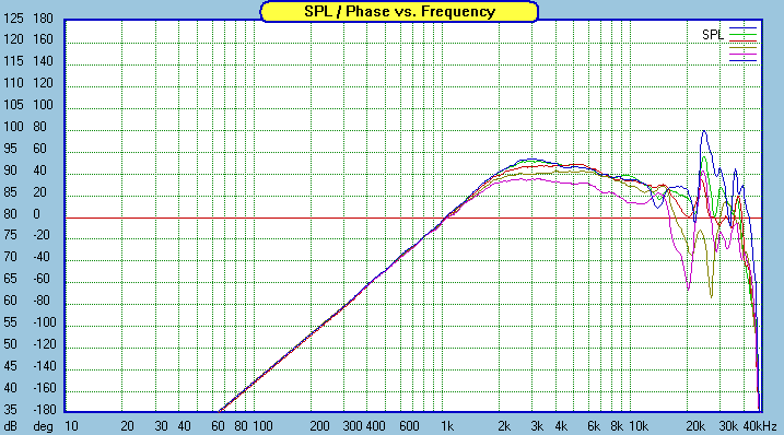
2) The waveguide will increase output on axis, beginning around 10khz or so. Basically the waveguide adds a 'boost' from 10khz and down
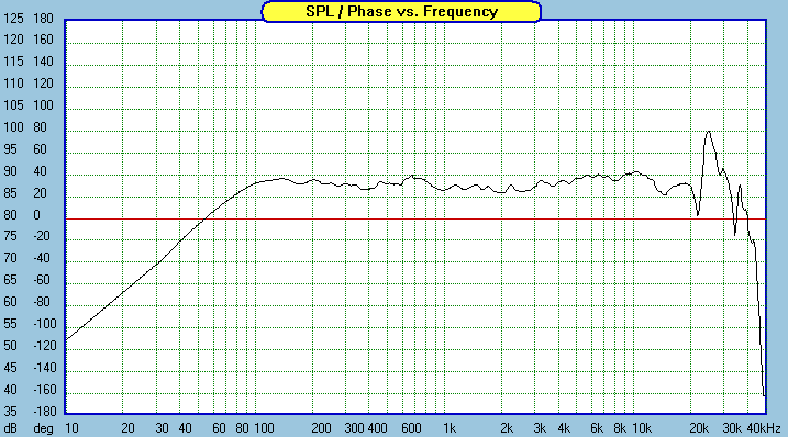
3) Here's the most important part. the boost from the waveguide is about six dB, and the cut from the capacitor is about 6dB. Put those together, and you end up with flat response.
4) Although the response ends up flat, the power handling ends up higher, because excursion is reduced and a fraction of the power is going into the tweeter.
Even though there's only a single cap on the tweeter, at the lower end of the tweeter's output, the slope of the filter will be much steeper than 6dB per octave, and it will *not* be phase coherent. In fact, to make it phase coherent would require quite a complex crossover; you might even have to apply *boost* to raise the output level below Fb! It looks to me that the waveguide and tweeter have a 'natural' rolloff of approximately 12dB/octave, so when you add that cap, you'll get something that exceeds 18dB/octave. (It's hard to say exactly, because the impedance of the tweeter will reduce the effectiveness of the cap at the tweeter's resonance.)
The graph above is the tweeter and waveguide from Zaph's measurements; here's the measurement of the complete system, post filter:

Last edited:
I am also a fan of adding light bulbs in series to protect the tweeters. Some claim they can hear that but I doubt it.
I hooked up a B52 landing light to an amp back when I was 14 or so. Yes you can hear it. Curiosity didn't kill the cat,... Uhhh amp!

I thought about this some more, and a single cap *might* form a 6dB/octave rolloff for about one octave. Here's why:
1) The waveguide adds about 6dB of boost beginning about 10khz. That frequency is due to the width of the waveguide at the throat - about 1.35", or 10000hz.
2) As frequencies get lower and lower, the waveguide gain approaches about 6dB. So at 5000hz, we have 6dB of gain from the waveguide.
3) If you set the lowpass xover of the crossover to 5000hz, the 6dB 'cut' of the xover will offset the 6dB 'boost' of the waveguide. The result is flat response at 5000hz.
4) At 2500hz, the crossover is reducing output by 12dB (since it's 6dB per octave), but the waveguide is only adding six dB. So the net effect is that 2500hz is down about 6dB. This is the frequency where you'd want to cross the midbass over. If you use that frequency, and if the rolloff on the midbass is correct, you'd end up with flat response that's in phase. I'm doing this all in my head, but if I'm not mistaken, the two drivers should be 'in phase' in the octave that's centered on the xover frequency. So basically 1800hz-3600hz should be in-phase.
As you get closer and closer to the natural rolloff of the tweeter, the phase will start to rotate, due to the rolloff of the tweeter. But at the same time, the tweeter isn't contributing much output at that point; most of the output is coming from the midbass.
Long story short - the combination of waveguide and a simple xover on the tweeter is a pretty nice solution, both from an amplitudue perspective, *and* from a phase perspective.
Last edited:
Long story short - the combination of waveguide and a simple xover on the tweeter is a pretty nice solution, both from an amplitudue perspective, *and* from a phase perspective.
My thoughts exactly (almost - I hadn't considered phase much past "well, they sum nice and flat").
The compromise I can see is that the large centre-to-centre distance puts a limit on the vertical off-axis behaviour, as Zaph notes.
Chris
I've seen this article on tweaking a Dayton tweeter Parts Express DIY Project
does a closed TL back chamber help flatten the impedance of various tweets? (similar to B&W and Vivid Audio designs)
does a closed TL back chamber help flatten the impedance of various tweets? (similar to B&W and Vivid Audio designs)
Last edited:
the waveguide "lump" response is effectively the driver's power response, when used on a constant directivity horn/waveguide- pretty much the same thing as the plane wave response. It's normal to have a 6dB fall off above some corner frequency, which, tuned right, is equal but opposite to the crossover cap. Incorporating this shaping effectively is part of why one needs complex XOs for horns- CD horns need that correction, but also, that correction can interact (badly) with impedance peaks if not managed carefully.
In some systems, the shaping capacitor can be tuned to also act as the high pass filter, below the max in the power response, where there's a 12dB slope often beginning.
In some systems, the shaping capacitor can be tuned to also act as the high pass filter, below the max in the power response, where there's a 12dB slope often beginning.
I've seen this article on tweaking a Dayton tweeter Parts Express DIY Project
does a closed TL back chamber help flatten the impedance of various tweets? (similar to B&W and Vivid Audio designs)
If done correctly, yes it would flatten the impedance peak nicely.
However, it would require that the tweeter has some kind of rear vent for the rear wave to be dissipated. This isn't a common feature*, so DIY use would be limited.
* for precisely the reason that the tweeter couldn't share a cabinet with a woofer without being directly subjected to the pressure from that woofer, which might well fling the tweeter diaphram across the room if adequate woofer displacement is achieved.
Chris
Interesting. Yes I understand that this mod would only work with tweets where the rear chamber can be got at.
- Status
- This old topic is closed. If you want to reopen this topic, contact a moderator using the "Report Post" button.
- Home
- Loudspeakers
- Multi-Way
- 1st order tweeters