You won't do any harm with audio grade polypropylene capacitors. 650V work best, but little need for anything too exotic IMO. Trouble is 8.2, 11 and 20uF are HUGE. You'd need to rebuild the board, which is actually a variation on the old KEF R 101 IMO. 😕
Getting rid of the ferrite coil for aircore will lead to similar size problems and a loss of sensitivity due to higher resistance. The tweeter coil won't benefit from change. Wirewound resistors work as advertised too.
Getting rid of the ferrite coil for aircore will lead to similar size problems and a loss of sensitivity due to higher resistance. The tweeter coil won't benefit from change. Wirewound resistors work as advertised too.
I like to change the capacitors and resistors for beginning, and leave the inductors untouched. While the suggested Clarity Cap or Mundorf don't have the values I need I checked the Sonic Cap Gen 1 and they have all values (CLICK HERE)...
Opinions please! 🙂
I read somewhere about by-passing capacitors with 0.1 or similar... Can someone explain this to me, please...
Opinions please! 🙂
I read somewhere about by-passing capacitors with 0.1 or similar... Can someone explain this to me, please...
Last edited:
You do realise you're going to run into some size issues here, my friend. Never mind cost. But I can only encourage you, since I like this sort of thing myself.
Before:
After:
Troels does this sort of stuff too:
SEAS constructions
Bypassing cheap caps with little good ones is a bit naff really. Get the proper jobs. Theory is the good ones take over at high frequency and smooth things. Not sure about that. 😉
What you'll get from the polypropylenes is a quieter smoother sound with more detail. Very noticeably better, IMO.
Before:
An externally hosted image should be here but it was not working when we last tested it.
After:
An externally hosted image should be here but it was not working when we last tested it.
Troels does this sort of stuff too:
SEAS constructions
Bypassing cheap caps with little good ones is a bit naff really. Get the proper jobs. Theory is the good ones take over at high frequency and smooth things. Not sure about that. 😉
What you'll get from the polypropylenes is a quieter smoother sound with more detail. Very noticeably better, IMO.
Last edited:
If you ask for available service aka matching pairs you probably will have a better chance of benefiting from a "better" sound.I read somewhere about by-passing capacitors with 0.1 or similar... Can someone explain this to me, please...
If you go the route of by-passing there's a lot of people and members here watching at your experiences and impressions. JBL did it but you can only find it in the top of the line speakers because it's more expensive.😎
Tolerance is 5%. Some custom values and tighter tolerances are available at additional cost.
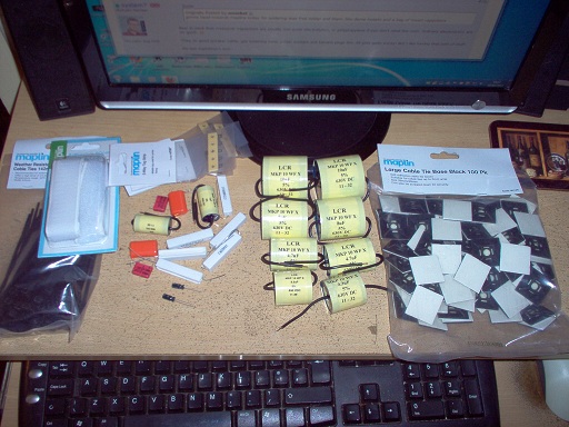
Did I show everybody my collection of polycaps? About £10 a pop for the 10uF jobbies. I couldn't be bothered to pay for silver or gold or anything, since these work:
Zobels across the tweeter are damn good at smoothing the top end too if you like to fiddle:
This 8.2 ohm 10W W/W and 0.68uF in series connected across the tweeter output, which suits most tweeters and don't muck up impedance too badly.
Zobels across the tweeter are damn good at smoothing the top end too if you like to fiddle:
An externally hosted image should be here but it was not working when we last tested it.
This 8.2 ohm 10W W/W and 0.68uF in series connected across the tweeter output, which suits most tweeters and don't muck up impedance too badly.
I think I made a decision and will go for Sonicap Gen 1 while they have all values I need. Called local store Partsconnexion (as suggested by TuanTran) however they do not have those values and to make a special order will take up to 8 weeks or more and even I do have time in my opinion this is to much waiting time. Anyway I just will place the order on the weekend, and while waiting I will tackle the painting project of the speakers (need to get all goodies for paint job). This weekend will be shopping time!
I find a really nice article in this matter READ HERE
I need some info in terms of reinforcing KEF iQ30 cabinets or damping methods.
Is anyone here willing to share... ? 🙂
I find a really nice article in this matter READ HERE
I need some info in terms of reinforcing KEF iQ30 cabinets or damping methods.
Is anyone here willing to share... ? 🙂
If it makes any difference any decent quality polyprop film cap will do and I wouldn't even bother replacing the inductors or the resistors, especially the resistors.
I need some info in terms of reinforcing KEF iQ30 cabinets or damping methods.
Is anyone here willing to share... ? 🙂
After much debate at diyaudio forum, I can present the simple answer how to reinforce cabinets. USE THE SAME MATERIAL AS THEY ARE MADE OF. Otherwise you turn them into sort of a wooden Xylophone, if you follow. Mixing hardwood with chipboard or MDF or plywood is very bad and creates resonance. Reinforcement behind the woofer baffle is a good thing. 🙂
My own opinion of polypropylene capacitors is that while some sound better than others, you really need to upgrade all the components together to get real improvement. So if you have an exceptional amp and CD player, you will wisely spend money on a crossover. But concentrate your resources on the weakest link. It's what Rotel call the "Balanced Design Concept".
If you ask for available service aka matching pairs you probably will have a better chance of benefiting from a "better" sound.
If you go the route of by-passing there's a lot of people and members here watching at your experiences and impressions. JBL did it but you can only find it in the top of the line speakers because it's more expensive.😎
For now I will not bypass HF but this is option I will further explore after I talk to some people for sure. While KEF denied but someone else is damn sure that iQ30 and XQ20 have the same drivers but different x-over I think it is worth exploring other options too.
I will ask for matching pairs of caps, for sure... Thx for suggestion and to be honest I thought of it but if you didn't mention I will just place a order... 😱
It's what Rotel call the "Balanced Design Concept".
Funny you mention Rotel there, while my end amp is Rotel RB-1050! 😉
If anyone wonders about my system components and while I am striving to mod iQ30, here they are:
Premap/Headphone amp: Antique Sound Lab MG OTL 32 DT
Amp: Rotel RB-1050
Tuner: Parasound TDQ-150
CD/DVD (temporary solution): Cambridge Audio DVD99 planing to get some good CD player
Speakers: PSB G-Design GB1 and KEF iQ30 and outstanding project with Jordan JX92S original drivers not the new one (it is on hold for now - no time to build cabinets)
Headphones: Sony MDR-7506; Beyerdynamic DT-931 (from 90's not the new ones);
TT: Sony PS-X9 (unfortunately broken but Sony is willing to repair it just need to ship TT to Sony BC - Vancouver)
Other: NAD AV 713; Denon AVR-588; Onkyo TX-8511; Luxman L-3; and some Sony and Yamaha DVD's;
I have my old stuff in Europe (in my house) but didn't get them here... T+A speakers, T+A Pre/End Amp combo; Marantz CD16 and Rotel CD players, Canton GLE70 speakers (from late 80's) and some Cardas and Kimber cables. 😉
Last edited:
I agree with the article: " All the bypasses sound bad ".
One more reason to leave bypass as an option for now... I might experiment later on. 😎
I was just reading the KEF iQ30 6moons review, RAART:
6moons audio reviews: KEF iQ30
Those cabinets look very well made and reinforced. I can't see how you'd better them really. The damping is a bit CHEAPISH with a roll of BAF wadding. Being a reflex, you probably want as little in the way as possible. It could be worth fixing some bitumen or car-door damping sheets to the sides and losing the wadding. I found a piece of rubber backed carpet tile on the back panel just like the put on office floors worked well with reflex. Secured with double-sided tape. The idea is to absorb the midrange a bit before it comes out of the reflex port. You don't want to overdo the absorbtion with reflex or you take away its liveliness.
These are a million miles away from a Tannoy dual-concentric, with paper bass laminated with titanium and metal dome tweeter. The tweeter is evidently not very efficient, so you don't have a lot of scope to modify the crossover. It looks like these low impedance speakers will always be standmounters rather than wall-mounted bookshelves to me. I'm a bit surprised how simple the crossover is, in fact. I'd have thought that bass unit would need more rolloff to avoid breakup.
Better capacitors are going to help, IMO. And a Zobel on the tweeter worth trying.
I forgot to mention but I did already was looking into this SOUND COAT as well as this Deflex sheet.
In regards of tweeter I do not know but I got this info "would you prefer I give you the values to the XQ20 instead? Steep 24db slope xover on the mid/tweeter vs. the 12db slopes on your iQ30, both which use the same driver in case you didn't know" and now I am a bit hesitating what to do...
Still waiting for those information from the same source. I am just wondering if anyone can verify if the XQ20 and iQ30 drivers are the same?
Mixing hardwood with chipboard or MDF or plywood is very bad and creates resonance.
As far as I am concerned I'd expect the opposite to be true. Using dissimilar materials, providing they are intrinsically well damped would only act to stop resonances from occurring, especially if they are laminated.
I was just reading the KEF iQ30 6moons review, RAART:
It could be worth fixing some bitumen or car-door damping sheets to the sides and losing the wadding.
These are not the same thing though are they? Bitumen sheets or damping pads affixed to the sides of the cabinet are there to prevent or help stop the enclosure from resonating.
Wadding on the other hand is there to absorb and scatter energy inside the cabinet and to help dissipate internal standing waves.
One one hand you do want to keep a ported enclosure relatively free from wadding, but at the same time you need enough to prevent issues from occurring. I believe Zaph has measurements showing this on his website.
I just was reading this:
"The iQ series cabinets are only 1/2" thick mdf laminate covered with minimal bracing. For the DIY'er you can reduce cabinet resonations in the iQ series by fiberglass coating the inside with fiberglass matte and bondo. I did it with my iQ series to get rid of the cabinet resonations, which does seem to make a mild improvement."
I think something is there...
I know Nuance, a Canadian speaker company, using only damping pads to cover all the wooden surfaces inside the enclosure of Nuance speakers. I believe that there is a good reason for Nuance using only damping pads for its speaskers. My Nuance bookshelf speakers (ported) sound very good and I like the sound of speakers with only damping pads.
When I modify a crossover of a speaker, I try to replace components with the same brand and type for capacitors or resistors unless the costs of some greater value capacitors are too high. I did many tests on many different brands of speakers and I like the sound of speakers with the same brand and type for capacitors or resistors in crossover networks. I like to replace resistors with higher wattage ones because I can hear the differences.Specially the resistor of the impedance equalization for woofer. Bass is cleaner (less distortion) with higher power resistor. I do not hear any difference if I replace resistors with the same wattage, higher quality ones.
- Status
- Not open for further replies.
- Home
- Loudspeakers
- Multi-Way
- x-over for Kef iQ30