Hello from the Apple Isle.
I purchased a pair of AT-60H 8R Stereo 100W pads. Then wired them in paralell for my 4R system. They work well and seem to handle the power at low levels, but I want to know if I am going to char them if i turn the volume up a bit and then wind back the pad, for example; from 6db of cut to 10db at 200WRMS
As mentioned earlier, the pads are rated at 100W (which watts I wonder)?
The datasheet quotes some power figures for three different levels of 'cut' under a specification loosely termed - 'rated power'.
For example;
RATED POWER: 2dB/50W, 6dB/35W, 12dB/25W.
QUESTIONS What are they on about?
Are they talking about the proportion of the system's power that is being diverted to the tweeter via the crossover? before the l-pad takes it's dissapation slice? or is it the 'remainder of the power that is divertet to the tweeter after xo and L-pad?
Are they talking about the accompanying amplifier's power rating, which is yet to be divided high and low via the xo filters and then cut by the L-pad?
Is this the power that the pads dissapate within their own windings?
The pads are a 'linear' wind and rotate for 300 degrees, SO, at what angles do 12db, 6db or 2db occur?
Does the L-Pad go before the xo? or does it wait it's turn?
How is the L-Pad wired schematically? (certainly not as per the circuit diagram in my datasheet).
This DATASHEET is misleading. I want to know how my attenuator works. I think this is a reasonable request of the manufacturer.
These are the data that I want on my datasheet, so I need the big-boys in China and Korea, Thailand and malaysia to provide that info next time they design or copy something and sell it on to me! - They should already know these parameters and therefore it costs them nothing to supply the information in a courteous way, and I really believe it is their duty. Anything less assumes prior knowledge and is just wong.
Cheers, Phil
Hi Phil. It's amazing how a simple component can generate so many questions, but it does 
The rated power seems to depend on how far you have them turned, An L-pad effectively dissipates what you are taking away from the driver, so it could be asked to dissipate between none, and all of the power meant for the tweeter.
As for how much in practice, take it slowly and push the volume levels and give them time to prove themselves. Monitor them with your hands near the case, but especially with your nose. But 50W is a lot of power to waste and not many tweeters would come close.
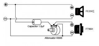
A typical L-pad (can't see your datasheet) has three terminals. The top one connects to the wire meant for the tweeter(+), The middle one goes to the actual tweeter(+), and the tweeter(-) wire goes to the bottom L-pad terminal and the actual tweeter(-).
You would normally put this next to the tweeter and connect the crossover to it. Normally there is less need for any impedance compensation when you use an L-pad but if you wanted to use such a filter for the tweeter's resonance, it's the only commonly used circuit item I'd put after an L-pad, I think.
The rated power seems to depend on how far you have them turned, An L-pad effectively dissipates what you are taking away from the driver, so it could be asked to dissipate between none, and all of the power meant for the tweeter.
As for how much in practice, take it slowly and push the volume levels and give them time to prove themselves. Monitor them with your hands near the case, but especially with your nose. But 50W is a lot of power to waste and not many tweeters would come close.
A typical L-pad (can't see your datasheet) has three terminals. The top one connects to the wire meant for the tweeter(+), The middle one goes to the actual tweeter(+), and the tweeter(-) wire goes to the bottom L-pad terminal and the actual tweeter(-).
You would normally put this next to the tweeter and connect the crossover to it. Normally there is less need for any impedance compensation when you use an L-pad but if you wanted to use such a filter for the tweeter's resonance, it's the only commonly used circuit item I'd put after an L-pad, I think.
Hello again Inductor!
I think you are right - I'm crying over spilt milk. The required attenuation is still within the scope of adjustment.
On the positive side;
PS I clicked that link of yours to take a peek - Real joinery! and the big vaccum tubes in the centre of the (pre?)amps look like milk bottles!
I think you are right - I'm crying over spilt milk. The required attenuation is still within the scope of adjustment.
On the positive side;
- the speakers were designed for my new Silicon Chip 20 Watt class A copy. So I will be dealing with only 10% of the power that I am using now.
- Those big cabinets work beautifully straight off the drawing board - this surprised me because they have a heap of plastic pipe inside which I thought may cause problems/vibes. I chose the pvc porting material despite this as I knew it would be the lightest alternative to MDF internal ducting.
- They are very very loud so they don't need to be driven hard - for example: I have been running them on my Silicon Chip ULD Mk.3 amp using less than one third of the power that my old Goodmans Magnum 150 speakers consume.
- I combined a 22Hz box with a 25Hz bass speaker in an attempt to get that punchy 'doof' sound that a kick drum makes, but this effect is less prevalent than in my last set of 30lt tower speakers that only had 6.5" drivers , 50Hz f0 and 50Hz box.
- The paint-job is a bit 'rough' as it has been too soggy and cold down here for the paint to harden off. I am postponing the final coat until next January when it warms back up for a couple of days.
- They are very difficult to move around as they weigh about the same as a catipillar dump-truck from Kalgourli.
PS I clicked that link of yours to take a peek - Real joinery! and the big vaccum tubes in the centre of the (pre?)amps look like milk bottles!
Last edited:
Hi there Al. I never used adjustable pads before but an old set of Goodmans Magnum 150's showed me their benifits.
All my filters for this set of speakers were modelled on the magnum's layout, but a thought just struck me.... I could remove the zobel circuit from the tweeters and this will have the effect of 'naturally' cutting the tweeter as the impedance will increase substantially along with frequency from about 3kHz upwards.
Does that sound right to you? I may be wrong, again!
By the way, I built that Silicon Chip amp you told me about and it sounds wicked on the bench. I used a 300VA 36V centre-tapped transformer, cooked up my own boards and used a few alternative components, but the HF response of this amp is loud and clear - of course there is good bass response also but the high end is like a bell and It is what I have been craving even though I didn't know it! My friends at the sheetmetal shop built me a couple of enclosures to suit - for 40 dollars each so I will have to slap a coat onto the galvanised steel to finish it off - might etch the galv slightly with some of the pcb etchant/cocktail, this will help the paint to stick.
Thanks for replying Allan and stay out of the wind and rain.
Cheers and bye for now. Phil
All my filters for this set of speakers were modelled on the magnum's layout, but a thought just struck me.... I could remove the zobel circuit from the tweeters and this will have the effect of 'naturally' cutting the tweeter as the impedance will increase substantially along with frequency from about 3kHz upwards.
Does that sound right to you?
I may be wrong, again!By the way, I built that Silicon Chip amp you told me about and it sounds wicked on the bench. I used a 300VA 36V centre-tapped transformer, cooked up my own boards and used a few alternative components, but the HF response of this amp is loud and clear - of course there is good bass response also but the high end is like a bell and It is what I have been craving even though I didn't know it! My friends at the sheetmetal shop built me a couple of enclosures to suit - for 40 dollars each so I will have to slap a coat onto the galvanised steel to finish it off - might etch the galv slightly with some of the pcb etchant/cocktail, this will help the paint to stick.
Thanks for replying Allan and stay out of the wind and rain.
Cheers and bye for now. Phil
If you want your frequency response to take on the shape of your impedance curve, this is one way but it will be tied in with the level. There is some sense to it and some people seem to like it. If you change your mind there are other ways to adjust the extreme top end.I could remove the zobel circuit from the tweeters and this will have the effect of 'naturally' cutting the tweeter as the impedance will increase substantially along with frequency from about 3kHz upwards.
Does that sound right to you?
- Status
- This old topic is closed. If you want to reopen this topic, contact a moderator using the "Report Post" button.
- Home
- Loudspeakers
- Multi-Way
- L-Pad (adjustable pads) power ratings