Just a small update,
My first try with carbon springs did not turned out very good, and I haven't done ant more experimented with it....maybe at a later time.
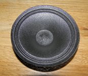
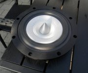
I have been trying to get the finish that I want on my cone, and I am pretty close now see pictures.
Take care
My first try with carbon springs did not turned out very good, and I haven't done ant more experimented with it....maybe at a later time.
I have been trying to get the finish that I want on my cone, and I am pretty close now see pictures.
Take care
Attachments
Alternative spring suggestion
I have an alternative idea for a spider: use metal toothpicks.
These have a handle of two steel wires closely turned around each other, and that makes a spring.
They come in various sizes, and each has a different bending ratio.
I tested some sizes and these go with a flex of a mm for the 0,75 mm green, 0,55 mm blue, 0,50 mm red.
The brush can be cut off with a razor; my idea that the part where the PVC wires are bonded in the spiral, that this area will be some damping: a good property.
My idea was to use the wires for a spider, spiraling them oblique not perpendicular to the voice coil former, fanning out. Having a small bend in all of them would allow a flex point.


(I once made a balsa wood PU arm with a shell structure suspended with blades made from a razor and that worked as a charm, res 6 Hz; all went well for several years) In the same way in the Axiom speaker a full range edgeless suspension was made with two crossing small blades for each suspension point.
I have an alternative idea for a spider: use metal toothpicks.
These have a handle of two steel wires closely turned around each other, and that makes a spring.
They come in various sizes, and each has a different bending ratio.
I tested some sizes and these go with a flex of a mm for the 0,75 mm green, 0,55 mm blue, 0,50 mm red.
The brush can be cut off with a razor; my idea that the part where the PVC wires are bonded in the spiral, that this area will be some damping: a good property.
My idea was to use the wires for a spider, spiraling them oblique not perpendicular to the voice coil former, fanning out. Having a small bend in all of them would allow a flex point.
I conceptualized the idea to use it for a Lowther spider (the standard spiders deteriorate fast) but in the end I decided not to spend a life in tuning and bought the superior type of rubber dubber spiders.
and bought the superior type of rubber dubber spiders.
(I once made a balsa wood PU arm with a shell structure suspended with blades made from a razor
and that worked as a charm, res 6 Hz; all went well for several years) In the same way in the Axiom speaker a full range edgeless suspension was made with two crossing small blades for each suspension point.Maybe someone can draw some inspiration from legendary H. A. Hartley (and H.J.Luth):
Some photos and look for patent US3160716.
Spiders are made from three layer fiberglass.
Some photos and look for patent US3160716.
Spiders are made from three layer fiberglass.
Attachments
Last edited:
Maybe someone can draw some inspiration from legendary H. A. Hartley (and H.J.Luth):
Some photos and look for patent US3160716.
Spiders are made from three layer fiberglass.
Another big advantage of such a spider assembly is that it allows you to reposition the cone in the magnet gap; slightly loosen the screws and reposition until a 10-20 Hz sine sounds good.
the inverse of the procedure with which you can position the magnet/gap in a Lowther; there you have to tighten the magnet to some degree, and hit the magnet with a piece of wood (I did it that way; and this works well with ceramic magnets).
My build:

I reduced the thickness to 1 mm; the pertinax plate was 2 mm. Well, thicker = stiffer and higher resonance I think.
albert
Last edited:
Just a small update,
My first try with carbon springs did not turned out very good, and I haven't done ant more experimented with it....maybe at a later time.
I have been trying to get the finish that I want on my cone, and I am pretty close now see pictures.
Take care
Nice project you got going there.
My own driver project is on idle for now, but that ought to change during the winter.
Magura
So why aren't more drivers made that way? Is it because it requires more manual labour? Or the components cost more? Or Kms(x) is less flat?Another big advantage of such a spider assembly is that it allows you to reposition the cone in the magnet gap; slightly loosen the screws and reposition until a 10-20 Hz sine sounds good.
the inverse of the procedure with which you can position the magnet/gap in a Lowther; there you have to tighten the magnet to some degree, and hit the magnet with a piece of wood (I did it that way; and this works well with ceramic magnets).
My build:
View attachment 368509
I reduced the thickness to 1 mm; the pertinax plate was 2 mm. Well, thicker = stiffer and higher resonance I think.
albert
Hi, Nice to see some new ideas. But triode_al I am not sure I fully understand, can you maybe make a little drawing. But I like the way you designed your spider, yours don't have the rotary motion... well done.
I have seen the way H. A. Hartley made his spider and others like that and it is one way to do it, but I am interested in reducing the areal of the spider. That way it will have less influence on the speaker..... But it is not a ease task, it still gives me a some problems.
Looking forward to see some pic's from your project Magura...
454Casull. I think the reason most manufacturers today, ( but some still do) don't use this is that it is more costly and more difficult to handle. Another think is that in the old days they was using a phenol based material, and it is not good for health.. it can courses cancer.
Hi, nice spiders
As pointed out there have been many attempts to produce a different (if not better) spider. Some of the ideas mentioned here i think i saw with Rulit's designs.
Frank, that is an awesome looking driver. Congrats!!!
Unfortunately i havent seen any DIY measures of Kms(x) for such drivers. Even to simulate the behavior is a very difficult task and it has been one of the reasons many stay away from these solutions.
But i think the biggest reason (and i may get shot for saying it) is that all these designs bring little or no value to the perceived sound, so manufacturers wont waste resources on this unless they want to market it as such.
What worries me most about these solutions is the uneven distribution of force on the voice coil former. Even with a 4 point cross connection to the chassis in transient times I think the voice coil will get deformed. Usually the dimensions and shape of the voice coil former are just about right to have any disturbing force on one end be reflected to the other end. So if you dont have the same connection all around the former i think it will wobble/rock. Ofcourse magnitude of this will depend on x.
Why not make a spider in a spider's web pattern. From some kind of wire like Frank suggested and this way the connection at the former will be firm because radius get smaller closer to the former and the wires will spread out going outer towards the frame connection. It wont radiate sound, it will have small added mass (to some degree) and it will distribute force equally.
I realize "distribute" is not the correct term... maybe only for restoring force but you get what i mean.
Anyways im working now on a tesla meter tool , want to map the field in the entire gap. I will post more when its ready but i finally got some hall sensors that are small enough and that can measure up to 3T after quite a search.
As pointed out there have been many attempts to produce a different (if not better) spider. Some of the ideas mentioned here i think i saw with Rulit's designs.
Frank, that is an awesome looking driver. Congrats!!!
So why aren't more drivers made that way? Is it because it requires more manual labour? Or the components cost more? Or Kms(x) is less flat?
Unfortunately i havent seen any DIY measures of Kms(x) for such drivers. Even to simulate the behavior is a very difficult task and it has been one of the reasons many stay away from these solutions.
But i think the biggest reason (and i may get shot for saying it) is that all these designs bring little or no value to the perceived sound, so manufacturers wont waste resources on this unless they want to market it as such.
What worries me most about these solutions is the uneven distribution of force on the voice coil former. Even with a 4 point cross connection to the chassis in transient times I think the voice coil will get deformed. Usually the dimensions and shape of the voice coil former are just about right to have any disturbing force on one end be reflected to the other end. So if you dont have the same connection all around the former i think it will wobble/rock. Ofcourse magnitude of this will depend on x.
Why not make a spider in a spider's web pattern. From some kind of wire like Frank suggested and this way the connection at the former will be firm because radius get smaller closer to the former and the wires will spread out going outer towards the frame connection. It wont radiate sound, it will have small added mass (to some degree) and it will distribute force equally.
I realize "distribute" is not the correct term... maybe only for restoring force but you get what i mean.
Anyways im working now on a tesla meter tool , want to map the field in the entire gap. I will post more when its ready but i finally got some hall sensors that are small enough and that can measure up to 3T after quite a search.
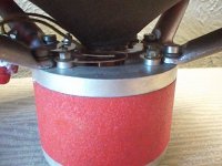
My spider in use. It is more like a crab by the way. But is is not a crappy spider.

The big black thing is the cone; it allows a large excursion. And because the pertinax is thin it does not only flex at the cone side. Nevertheless it would be nice to see a pertinax model in polarized light or a simulation would give a lot of insight in the flexing characteristics.
Why such a teeny weeny small spider?
Well, I once made a spider from strings so this is very very sturdy.
But still Jensen etcetera in the fifties had thicker ones. Magnavox seems to have the original patent from around 1938; all others are variants.
I also like the use of such a spider in the center of the pole piece. Atelier Rullit experiments all the time; he uses old and modern materials that have nice characteristics.
albert
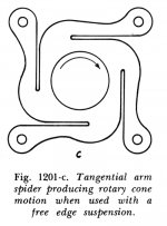
The idea for a tooth-pick spider.

As you can see in this abstract lay-out the toothpicks radiate out from the coil edge, tangentially.
This implies of course the cone will twist a bit as it moves to and fro. But is should be a little; depending of course on the linear displacement (max excursion).
As you can see in this abstract lay-out the toothpicks radiate out from the coil edge, tangentially.
This implies of course the cone will twist a bit as it moves to and fro. But is should be a little; depending of course on the linear displacement (max excursion).
Hi, nice spiders
What worries me most about these solutions is the uneven distribution of force on the voice coil former. Even with a 4 point cross connection to the chassis in transient times I think the voice coil will get deformed. Usually the dimensions and shape of the voice coil former are just about right to have any disturbing force on one end be reflected to the other end. So if you dont have the same connection all around the former i think it will wobble/rock. Ofcourse magnitude of this will depend on x.
Agree, this worried me too.
But hey, a voice coil former will probably wobble too (standing waves); some manufactures have over one inch between the coil and the base of the cone (the 'neck'). But that is just though experiment of course.

Ok now I know what you mean with the toothpicks spider, thanks. But I see some problem with it. First, the way the toothpicks are placed will create a rotary motion when moving up and down. This will accumulate energy in the toothpicks, because the voice coil is fixed at the cone and the cone will try to hold it in place. Also I am not sure if it's stiff in the sideways movement.
H. A. Hartley solved this in a very neat way. The voice coil is not connected to the spider at all but only the main cone is attached to the spider, the centre cone with the voice coil is the attached to the main cone. This way there will be no outside mechanical interference to the voice coil, other than the point where the voice coil is mounted to the main cone.
The way I am thinking to reduce the stress on the voice coil is to make the former thicker (0.4mm) just over to turns, it will cost me about 100 microgram. Maybe I will try to make the hole thing thicker, this will also make it a better conductor to the cone. But I still need a bright idea for the spider.
Take care
Has anyone really looked into using ferrofluid with a high saturation rating? I am in the process of acquiring some for my mbl project. The following is the information you'll need to get the perfect custom fluid built to your motors needs. http://imgur.com/7Zcs1Ee,9J0wzjE,o53RalD,49EDsKc#0
Last edited:
For a driver with low Xmax it can be possible to scale up a suspension typically used on compression drivers.Hi, nice spiders
As pointed out there have been many attempts to produce a different (if not better) spider. Some of the ideas mentioned here i think i saw with Rulit's designs.
Frank, that is an awesome looking driver. Congrats!!!
Unfortunately i havent seen any DIY measures of Kms(x) for such drivers. Even to simulate the behavior is a very difficult task and it has been one of the reasons many stay away from these solutions.
But i think the biggest reason (and i may get shot for saying it) is that all these designs bring little or no value to the perceived sound, so manufacturers wont waste resources on this unless they want to market it as such.
What worries me most about these solutions is the uneven distribution of force on the voice coil former. Even with a 4 point cross connection to the chassis in transient times I think the voice coil will get deformed. Usually the dimensions and shape of the voice coil former are just about right to have any disturbing force on one end be reflected to the other end. So if you dont have the same connection all around the former i think it will wobble/rock. Ofcourse magnitude of this will depend on x.
Why not make a spider in a spider's web pattern. From some kind of wire like Frank suggested and this way the connection at the former will be firm because radius get smaller closer to the former and the wires will spread out going outer towards the frame connection. It wont radiate sound, it will have small added mass (to some degree) and it will distribute force equally.
I realize "distribute" is not the correct term... maybe only for restoring force but you get what i mean.
Anyways im working now on a tesla meter tool , want to map the field in the entire gap. I will post more when its ready but i finally got some hall sensors that are small enough and that can measure up to 3T after quite a search.
http://www.supplierlist.com/photo_images/38008/REPLACEMENT_REPAIR_2425.jpg
Although I don't know if there is any self-torsion throughout the excursion.
In my layout I have straight wires; but it is easy to have a bend in them; and then that bend allows for a slack. Subsequently it is possible to have two from a connection point going in two directions.
This solves the twisting motion completely.
This solves the twisting motion completely.
One can then weave a little string through the toothpick wires to dampen them, creating a kind of cobweb
Has anyone really looked into using ferrofluid with a high saturation rating? I am in the process of acquiring some for my mbl project. The following is the information you'll need to get the perfect custom fluid built to your motors needs.
I use ferrofluid and have tested a lot of variants...
The best audio quality are without ferrofluid, but I use it to center the voice coil so it is needed. Soon I will test out a minimalistic spider design that have only one mission -> center the voice coil. If I used the variant with stiffer cloth surround I can avoid the ferrofluid / spider, but with the silk surround some centering are required.
Oh yeah I know and I posted before with the same reply but some of you seem to not be using the field coil design so I was just wondering.Well, ferrofluid will not work for me becouse I an useing a feild coil, it will make a mess when turned of
- Home
- Loudspeakers
- Multi-Way
- Project Ryu - DIY Field Coil Loudspeaker