Hi Paul, thank you. Would be nice to share some of your thoughts on field coil, specially if you've done some compression drivers.
Boscoe, Vas will most certainly be of high value 150-250l because of low Fs and Mms. As a target i have set 50Hz for Fs. I don't really want to go above this value.
I will use this driver in horn so Vas, Fs don't really mean much on their own but rather the elements that give these values like Mms, Cms, SD make the story.

Hi,
I was able to do some more testing and measurements this weekend and i could plot some important functions.
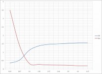
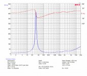
First plot shows flux density B against field coil current. It also shows Qes, measured for a specific cone assembly ofc but i thought it can be useful to see it.
You will notice the gap saturates around 1.55T and going beyond 2.4-2.5 drive current is not really necesary, altho i measured difference of 0.5-0.7db in SPL at 4 Amps before compression kicks in.

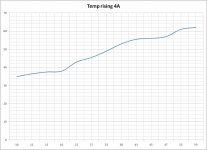
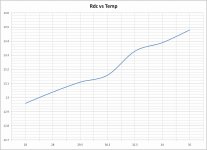
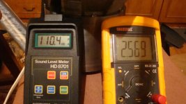
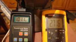
At 2.2 Amps the temperature stayed at room level of 28deg C, at 2.5 Amps within 1 hour went to 29deg C. Below you can see the temp plot with the field coil at 4 Amps within 1 hour frame. Previously it ran at 2.5 Amps so it was pretty warmed up.

After the hour in the next 15 min it stayed at around 62deg C and after that i stopped it.
At 4 Amps once B won't go higher, beta=(BL)^2/Rdc will start to drop because of Rdc.

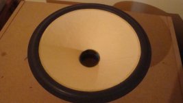
I'm not ready yet to post some of the impedance or Fr graphs (unless you want to see some really messy ones haha) but with the white cone pictured a post above with a Mms reaching 20.4g i got to 7.38% calculated efficiency and 100.8dB/w/m average sensitivity. The bad news is that i was way off regarding inductance.
Yea, i got the correct value when air cored but once placed in that gap its not the same.
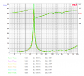
A whooping 3.2mH measured 1kHz (average) took down all response beyond 3-3.5Khz. There was a small resonance around 1kHz so at first i blamed it for the high Le. Surely enough with lower current within fieldcoil and not so much energy to excite resonance Le value drops to 2mH. Curious thing.
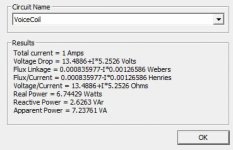
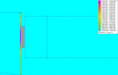
So i went back to solving the AC problem. Le= (N*phi)/i, where Le is inductance, N is number of turns, phi is rate of change of AC flux and i is current through voicecoil.
N*phi is the quantity known as flux linkage and FEMM when solving AC problems calculates it. In fact it actually calculates Le as Flux/Current.
Here is result with current voice coil no shorting ring:
3.9mH pretty close to the real world.

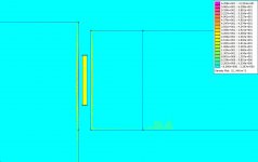
While we are at it, current density in plates at 1kHz:

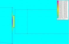
10Khz:

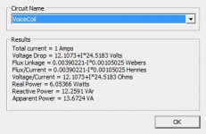
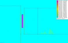
Adding 0.25mm thick copper faraday ring results in:
0.83mH

1kHz:

10khz:

I will redesign the voice coil as i want Le under 0.5mH. I will need to use thicker wire. The journey continues...
I was able to do some more testing and measurements this weekend and i could plot some important functions.
First plot shows flux density B against field coil current. It also shows Qes, measured for a specific cone assembly ofc but i thought it can be useful to see it.
You will notice the gap saturates around 1.55T and going beyond 2.4-2.5 drive current is not really necesary, altho i measured difference of 0.5-0.7db in SPL at 4 Amps before compression kicks in.
At 2.2 Amps the temperature stayed at room level of 28deg C, at 2.5 Amps within 1 hour went to 29deg C. Below you can see the temp plot with the field coil at 4 Amps within 1 hour frame. Previously it ran at 2.5 Amps so it was pretty warmed up.
After the hour in the next 15 min it stayed at around 62deg C and after that i stopped it.
At 4 Amps once B won't go higher, beta=(BL)^2/Rdc will start to drop because of Rdc.
I'm not ready yet to post some of the impedance or Fr graphs (unless you want to see some really messy ones haha) but with the white cone pictured a post above with a Mms reaching 20.4g i got to 7.38% calculated efficiency and 100.8dB/w/m average sensitivity. The bad news is that i was way off regarding inductance.
Yea, i got the correct value when air cored but once placed in that gap its not the same.
A whooping 3.2mH measured 1kHz (average) took down all response beyond 3-3.5Khz. There was a small resonance around 1kHz so at first i blamed it for the high Le. Surely enough with lower current within fieldcoil and not so much energy to excite resonance Le value drops to 2mH. Curious thing.
So i went back to solving the AC problem. Le= (N*phi)/i, where Le is inductance, N is number of turns, phi is rate of change of AC flux and i is current through voicecoil.
N*phi is the quantity known as flux linkage and FEMM when solving AC problems calculates it. In fact it actually calculates Le as Flux/Current.
Here is result with current voice coil no shorting ring:
3.9mH pretty close to the real world.
While we are at it, current density in plates at 1kHz:
10Khz:
Adding 0.25mm thick copper faraday ring results in:
0.83mH
1kHz:
10khz:
I will redesign the voice coil as i want Le under 0.5mH. I will need to use thicker wire. The journey continues...
Attachments
-
 VoiceCoil v2_ring Ind 1khz.jpg33.8 KB · Views: 83
 -
 VoiceCoil v1 Ind 1khz.jpg35.1 KB · Views: 86
 -
 TvsI_measured.jpg122.3 KB · Views: 90
 -
 RevsT_measured.jpg122.2 KB · Views: 92
 -
 Current density plates 10khz.jpg95.6 KB · Views: 81
 -
 Current density plates 10khz FRing.jpg96.3 KB · Views: 77
 -
 Current density plates 1khz.jpg93.2 KB · Views: 95
 -
 Current density plates 1khz FRing.jpg92.9 KB · Views: 96
 -
 BvsI_measured.jpg122.3 KB · Views: 91
Very nice project!
The basket can be made easy and universal as Audio Technology Flex-Unit:
http://audiotechnology.dk/files/Dimensions_Drivers.pdf
The basket can be made easy and universal as Audio Technology Flex-Unit:
http://audiotechnology.dk/files/Dimensions_Drivers.pdf
Hello,
Took a day off from work today to try and push things forward with this project.
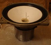
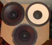
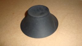
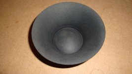
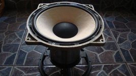
A few days ago, i fitted a factory made curved cone. A bit heavy for my taste (17g just the cone). I also run out of cloth suspensions so i used rubber foam single roll type this time.
The cone is shallower so another basket was used. I used the first type voice coil with the high inductance.
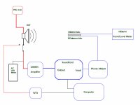
Today i did some more measurements to determine where am i standing on the mechanical and acoustical side. Below is a sketch of measurement setup i am using.

Impedance Measurements:
First measurements showed something going on in the 1Khz area. This made measuring Le with precision very difficult and the results were doubtful. But as i showed in some post above the FEM calculations pretty much confirms it.
Different spider, surround and cone shows similar behavior in that region, but i observed that lighter cones tend to amplify this effect.
I have done a few calculations, as i even suspected the chamber inside the motor structure would form a resonant circuit somehow but it doesn't check out.
At this point i have a couple of suspects. One is the construction of the voicecoil itself. The inside/outside dual coils in parallel might not have been the best idea. It sure doesn't help at all with inductance, just keeps the Re at good value for a good BL. The other is the suspension system. I used soft spiders as i like the GOTO principle (High magnetic force and as little mechanical resistance as possible) however it might be too soft to handle all the vibrational modes of such light cone.
Here are some curves taken in chronological order:


Trying a number of spiders, surrounds and cones smoothed it up a bit but i will wait and see how things will change with the new voice coil.
Also to my tastes, i like better the cloth triple roll surround, but of course its a component and its usage is key factor. The reason i like it is that from my results it has the least contribution to the overall moving mass.
Acoustic Measurements:
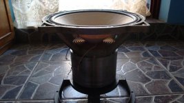
First pictures i am proud of Sine wave 1kHz.


Measurements done outside 1m high from ground, 2m closest wall, 1 m mic distance, driver free air.
This weekend i will mount it on a baffle, i think 1.5mx1.5m.

Took a day off from work today to try and push things forward with this project.
A few days ago, i fitted a factory made curved cone. A bit heavy for my taste (17g just the cone). I also run out of cloth suspensions so i used rubber foam single roll type this time.
The cone is shallower so another basket was used. I used the first type voice coil with the high inductance.
Today i did some more measurements to determine where am i standing on the mechanical and acoustical side. Below is a sketch of measurement setup i am using.
Impedance Measurements:
First measurements showed something going on in the 1Khz area. This made measuring Le with precision very difficult and the results were doubtful. But as i showed in some post above the FEM calculations pretty much confirms it.
Different spider, surround and cone shows similar behavior in that region, but i observed that lighter cones tend to amplify this effect.
I have done a few calculations, as i even suspected the chamber inside the motor structure would form a resonant circuit somehow but it doesn't check out.
At this point i have a couple of suspects. One is the construction of the voicecoil itself. The inside/outside dual coils in parallel might not have been the best idea. It sure doesn't help at all with inductance, just keeps the Re at good value for a good BL. The other is the suspension system. I used soft spiders as i like the GOTO principle (High magnetic force and as little mechanical resistance as possible) however it might be too soft to handle all the vibrational modes of such light cone.
Here are some curves taken in chronological order:
Trying a number of spiders, surrounds and cones smoothed it up a bit but i will wait and see how things will change with the new voice coil.
Also to my tastes, i like better the cloth triple roll surround, but of course its a component and its usage is key factor. The reason i like it is that from my results it has the least contribution to the overall moving mass.
Acoustic Measurements:
First pictures i am proud of
Sine wave 1kHz.
Measurements done outside 1m high from ground, 2m closest wall, 1 m mic distance, driver free air.
This weekend i will mount it on a baffle, i think 1.5mx1.5m.
Attachments
-
 DSC03003.JPG559.1 KB · Views: 109
 -
 DSC02995.JPG485.6 KB · Views: 83
 -
 DSC02994.jpg492.3 KB · Views: 93
 -
 Imp_Ryu0F1.jpg168.6 KB · Views: 100
 -
 Imp_Ryu0C1.png122.4 KB · Views: 101
 -
 Imp_Ryu0B2.jpg191.1 KB · Views: 96
 -
 Imp_Ryu0B1.jpg167.9 KB · Views: 99
 -
 Imp_Ryu0A1.jpg149.6 KB · Views: 103
 -
 Meas_setup.jpg44.1 KB · Views: 166


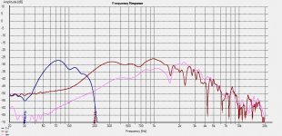
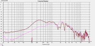
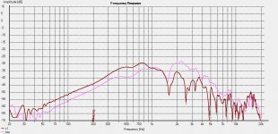
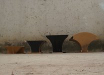
I had no baffle ready but i did had some mid horns for testing, from left to right i will number them 1,2,3,.. The pink trace is the driver in free air with 1khz at around 100dB.

Horn 1:

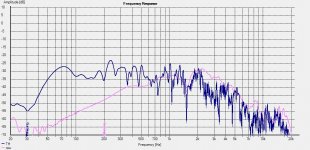
Horn 2:

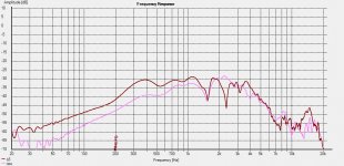
Horn 3:

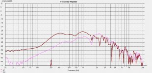
Horn 4:

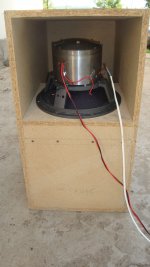
I also tested a 50Hz TH:


The way i will use the driver would be a BLH + FLH kinda in this config (dont mind the slopes ):

Next i will measure off axis and then the new voice coil will enter the scene.
Horn 1:
Horn 2:
Horn 3:
Horn 4:
I also tested a 50Hz TH:
The way i will use the driver would be a BLH + FLH kinda in this config (dont mind the slopes
):
Next i will measure off axis and then the new voice coil will enter the scene.
Attachments
Last edited:
Weekends are just too short...
Here is this last 2 weeks update:
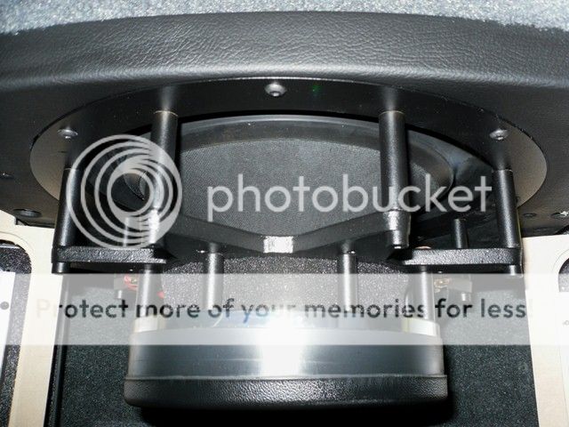
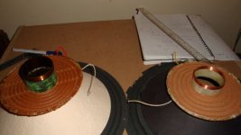
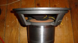
New voice coils were tested. Similar with the ones from Beyma 12G50. 9mm heigh 8ohms, 6mm heigh 6ohms 4mm heigh 4ohms . Shorting rings were imployed. One at the base of the magnetic gap and the other right in the gap along the voicecoil. Didnt take pics of voice coils before i installed them but below you can see the 6 ohms in the left and the older 16 ohms to the right

Inductance droped as expected and high frequency extension was easily noticeable. One thing sure checked out during experimentation and that is the most important aspect regarding the shorting ring is the copper quality. The location where the ring is positioned is important but not as much as the electrical resistance... at least in my implementation of underhung motors.
Le droped to 1mH with the 9mm VC and to 0.4mH with the 4mm VC
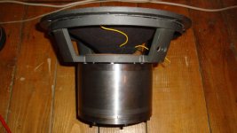
Testing showed the most contribution in inductance reduction came from the thick ring placed near the low end of the magnetic gap as in the picture below:


Whizzer cone was also added. It is clear now that at such high diameters curved cones have a clear advantage over straight ones but i guess this is just verifying the known facts. Trouble is the curved cones i have available and the ones that i made from layers of washi paper are pretty heavy with a mean value of 18g. Adding all up turns to a Mms between 30-35g.
Working with a factory made whizzer cone model and testing it with about 5 different cones both straight and curved and weighting between 9 and 18g i could see that the interaction between the whizzer and the main cone was constistent in each case.


The pictures are not very artistic and some elements are not very esthetic but keep in mind its just a prototype.
As a first conclusion the gap width will be reduced in the final motor design as the space for shorting ring is no longer required. The thicker ring placed under the gap will be used alone.
Here is this last 2 weeks update:
New voice coils were tested. Similar with the ones from Beyma 12G50. 9mm heigh 8ohms, 6mm heigh 6ohms 4mm heigh 4ohms . Shorting rings were imployed. One at the base of the magnetic gap and the other right in the gap along the voicecoil. Didnt take pics of voice coils before i installed them but below you can see the 6 ohms in the left and the older 16 ohms to the right
Inductance droped as expected and high frequency extension was easily noticeable. One thing sure checked out during experimentation and that is the most important aspect regarding the shorting ring is the copper quality. The location where the ring is positioned is important but not as much as the electrical resistance... at least in my implementation of underhung motors.
Le droped to 1mH with the 9mm VC and to 0.4mH with the 4mm VC
Testing showed the most contribution in inductance reduction came from the thick ring placed near the low end of the magnetic gap as in the picture below:
Whizzer cone was also added. It is clear now that at such high diameters curved cones have a clear advantage over straight ones but i guess this is just verifying the known facts. Trouble is the curved cones i have available and the ones that i made from layers of washi paper are pretty heavy with a mean value of 18g. Adding all up turns to a Mms between 30-35g.
Working with a factory made whizzer cone model and testing it with about 5 different cones both straight and curved and weighting between 9 and 18g i could see that the interaction between the whizzer and the main cone was constistent in each case.
The pictures are not very artistic and some elements are not very esthetic but keep in mind its just a prototype.
As a first conclusion the gap width will be reduced in the final motor design as the space for shorting ring is no longer required. The thicker ring placed under the gap will be used alone.
Attachments
I have done alot of measuring and testing, time is the enemy and i wont post all of them but i will give a couple of
examples to highlight a few of the problems.
There was also a small loss of data during a power crash and after system rebooted i found that holm hasnt saved any
of the measurements from that session (whole 49 fields!). However i always run one more app in parallel to save data
in txt format for archiving. Holm has the easy way of gating but after a few hourse i could do that manually.
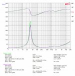
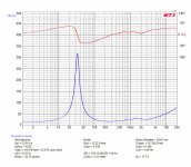
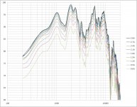
The measurements presented below are for a curved cone, foam half roll surround and linear spider. System resonance
roughly 50Hz.
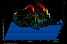
Impulse response is shown in a time delta of 10ms and frequency response gated at 5ms. Resolution 1/96 octave.
As picture will show, field coil was fed in 0.3A steps starting from 0.6A.


As you can notice the field coil drive current doesn't affect much the shape of the curves, just very small
differences. It does affect magnitude on all curves tho. I also had 30,45,60 degrees measurements for this example
but these were lost. There is also an increase in distorsion level with decreasing current, i will repeat
measurements with the next test cone/setup.
Ofcourse a deep hole in response can be observed and i will get back to that soon.

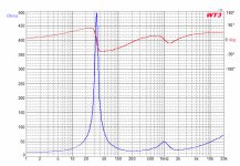
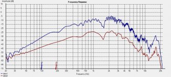
I also prepared a cone for a mid-bass unit, a 41g Mms. I measured as well from 0.6A to 3A drive current but i will
just post the overlay image and impulse for 2.1A with a 5ms time frame.


You can find the files in higher resolution in the attached zip.
examples to highlight a few of the problems.
There was also a small loss of data during a power crash and after system rebooted i found that holm hasnt saved any
of the measurements from that session (whole 49 fields!). However i always run one more app in parallel to save data
in txt format for archiving. Holm has the easy way of gating but after a few hourse i could do that manually.
The measurements presented below are for a curved cone, foam half roll surround and linear spider. System resonance
roughly 50Hz.
Impulse response is shown in a time delta of 10ms and frequency response gated at 5ms. Resolution 1/96 octave.
As picture will show, field coil was fed in 0.3A steps starting from 0.6A.
As you can notice the field coil drive current doesn't affect much the shape of the curves, just very small
differences. It does affect magnitude on all curves tho. I also had 30,45,60 degrees measurements for this example
but these were lost. There is also an increase in distorsion level with decreasing current, i will repeat
measurements with the next test cone/setup.
Ofcourse a deep hole in response can be observed and i will get back to that soon.
I also prepared a cone for a mid-bass unit, a 41g Mms. I measured as well from 0.6A to 3A drive current but i will
just post the overlay image and impulse for 2.1A with a 5ms time frame.
You can find the files in higher resolution in the attached zip.
Attachments
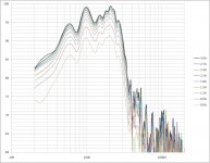
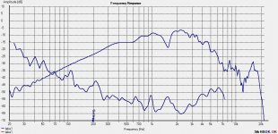
The drop in response around 4kHz was present with both the 1mH and 0.4mH Le voicecoils.
Looking at the graphs and comparing with measurements done without whizzer it seemed to me
that the maine cone fails to meet the whizzer at a high enough frequency or the whizzer
fails to meet the cone at a low enough frequency. Kinda like a 2 way xover with too far
apart xover points. I figured that the added mass of the whizzer lower the highest
frequency the cone would respond to.
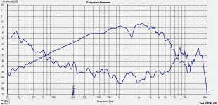
So i made another cone, straight this time with a mass of 8g (just the cone) in the hope
that it will reach a higher frequency when the whizzer is added.
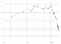
As you can see below the drop is not so pronounced anymore.

This pretty much sums it up for the past two weeks. 10Khz were reached, the push for the
last octave is on going. I'm still working on the best voice coil version and meanwhile
working on smoothing frequency response.
The previous 1.5kHz dip in FR i believe it was caused by a foam surround i used having a
wider roll and being a little thiner in material. Probably didnt provide a good cone
termination.
Thats about it for tonight. If you have any questions, ideas, thoughts i would be happy to
hear them.
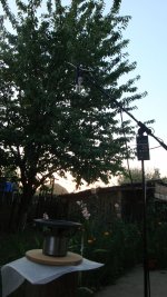
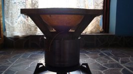
Below are just some shots i took with the driver:


Looking at the graphs and comparing with measurements done without whizzer it seemed to me
that the maine cone fails to meet the whizzer at a high enough frequency or the whizzer
fails to meet the cone at a low enough frequency. Kinda like a 2 way xover with too far
apart xover points. I figured that the added mass of the whizzer lower the highest
frequency the cone would respond to.
So i made another cone, straight this time with a mass of 8g (just the cone) in the hope
that it will reach a higher frequency when the whizzer is added.
As you can see below the drop is not so pronounced anymore.
This pretty much sums it up for the past two weeks. 10Khz were reached, the push for the
last octave is on going. I'm still working on the best voice coil version and meanwhile
working on smoothing frequency response.
The previous 1.5kHz dip in FR i believe it was caused by a foam surround i used having a
wider roll and being a little thiner in material. Probably didnt provide a good cone
termination.
Thats about it for tonight. If you have any questions, ideas, thoughts i would be happy to
hear them.
Below are just some shots i took with the driver:
Attachments
If you need pointers for the carbon stuff, let me know.
Magura
That would be great.
That would be great.
Drop me a mail then, and I'll see if I can sort you out.
Magura
- Home
- Loudspeakers
- Multi-Way
- Project Ryu - DIY Field Coil Loudspeaker