There are a couple of ways to go spider less. One way is to have a pole piece the same width as the inner diameter voice coil and have them lubed with Teflon. Though this will cause rubbing at low volumes. The second is merely the addition of ferro-fluid with the right centering force. If the motor has a high magnetic flux this isn't too much of a concern.
Oh yeah sorry I forgot who I was talking to. There more ways try a patent search for some ideas. I have heard of active restoring force. I also know of a company using a center rod which is attached to the voice coil? which pushes on a spongy material to act as a restoring force. maybe you guys could experiment with fiberglass rods attached at specific points for a restoring force
Why not? The gap will have the strongest field, right?Yes, but ferro-fluid is not an option for field coil units.
Nick hit the nail on the head, no field, no containment. Ferrofluid beats a hasty retreat with some help from gravity..
IMLE some of it escapes over time anyway. I've seen it wick out of the gap some drivers.
Drivers with large displacements (xmax) may also have problems with ferrofluid pumping out of the gap.
IMLE some of it escapes over time anyway. I've seen it wick out of the gap some drivers.
Drivers with large displacements (xmax) may also have problems with ferrofluid pumping out of the gap.
Nick hit the nail on the head, no field, no containment. Ferrofluid beats a hasty retreat with some help from gravity..
IMLE some of it escapes over time anyway. I've seen it wick out of the gap some drivers.
Drivers with large displacements (xmax) may also have problems with ferrofluid pumping out of the gap.
Did you seen it with drivers where it is placed only between the polepiece and former? Or only if there is fluid on both sides? The inner side is very smooth the outerside is not that smooth because of the windings. Also need good venting holes because of building up pressure under the gap. You can combine field coil with normal magnet so if the electro magnet won't work there is just enough flux to held the fluid in place. just a thought.
Hentai, Sorry I looked for the paper about 1khz distortion but couldn't find it anymore. I'm sure I read it is from the spider or surround but was the author correct? that's the question...
From my test i believe that spike was caused by transition between former and cones. I have tried different surrouds and spiders but still showed the peak at around 1khz but masses of vc and cones were always very close. The glue i used at those joints created a small compliance between the cones. when i made that compliance larger i was able to shift the peak in frequency indicating that the assumptions are correct.
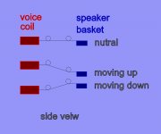
I have made some changes for the spring system. With the other system I would get tension energy at the joints, due to the twist of the spring when moving up and down. This is massive reduced with the new two loop springs, this will keep the two spring- joint close to 0° angle when moving becouse most of the flexing will be between the two loops. See picture.
Take care
Take care
Attachments
Last edited:
Hi, just a little update.
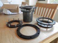
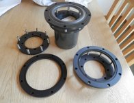
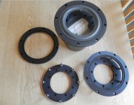
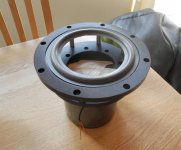
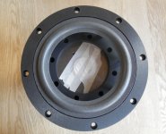
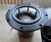
Just pick up the parts for the basket for the unit, man I am exited.... It is made from 10mm aluminium and the spacers made of stainless steel, they should be able to hole the field coil. Here is some pic's.
Take care
Just pick up the parts for the basket for the unit, man I am exited.... It is made from 10mm aluminium and the spacers made of stainless steel, they should be able to hole the field coil. Here is some pic's.
Take care
Attachments

Hi, just a little update.
Just pick up the parts for the basket for the unit, man I am exited.... It is made from 10mm aluminium and the spacers made of stainless steel, they should be able to hole the field coil. Here is some pic's.
Take care
Very nice Frank. I like this frame design a lot. Much stronger then a normal frame. Looks cool too.
nick
Frank,
Have pondered about using the two spring system myself. Do you think it necessary to connect the loops to say carbon pultruded tubes or carbon ribbon on edge would improve action by forcing the bending moment only at the springs?
Also using two springs per joint each turned opposite to the other when attached as mentioned above zero's out torque twist and giving you exceptional lateral stability a single point of a three point mount could never achieve.
Frank,
Have pondered about using the two spring system myself. Do you think it necessary to connect the loops to say carbon pultruded tubes or carbon ribbon on edge would improve action by forcing the bending moment only at the springs?
Also using two springs per joint each turned opposite to the other when attached as mentioned above zero's out torque twist and giving you exceptional lateral stability a single point of a three point mount could never achieve.
Well I am no expert in spring suspension. But if you use carbon tubes you will ad a little bit of weight, but you can use the carbon tube to adjust the compliance of the springs that is a nice feature. A good thing is if you glue the carbon tubes to the voice coil former, you will have more surface and a better connection to the voice coil former.
Using two springs turned opposite to the other is a great idea, and considering the low mass of the springs it will give you no problems.
Hentai, Yes the 8 holes is for mounting the unit in the cabinet. 8 times 6mm screws should hole it in place.
Take care
The mass of what little carbon used would be very low. For example a 1 mm rod 1m long weighs less than a gram. Cannot measure in the microgram range atm. Down to about 0.1g is the best I can do with out modifying the scale with an output from the strain guage so I can feed it into my Fluke 867b.
Hi Grebster
I agree the gain in weight with the carbon tubes will bee next to non, But on the other hand even if the weight was as high as a normal spider you still would have virtually no surface areal... So it is a win-win situation. I have been thinking if it would be better to use nylon wire, the on that is used for fishing..any thoughts on that?
May I ask what kind of unit are you building, if you have some pictures it would bee great if you would post them here.
I haven't looked into using fishing line in decades, would need to look into the new formulations available today. Hopefully they would be better behaved now than then when heated. Slowly creeping up on the temp and lowering it to form the loop. I would think very fine spring steel would work better. Don't know of anyone that makes springs from carbon tow at this scale LOL
Tangically attaching them in a V should help. Have these loops oppose each other along the length.
Tangically attaching them in a V should help. Have these loops oppose each other along the length.
I'm curious about your surrounds. It seems most are normal half rolls.They create less resistance to the movement of the cone, don't they? So why are they alway on drivers that have a low sensitivity? Or is that just circumstantial? I'm still going to toy around with my diy cones on the jbl frames I've got. I'm just wondering iv I would gain a few db in sensitivity by using a foam half roll surround.
I know in lower power use it won't cause problems that it would in pro use.
I've also been wondering if it would be possible to make my own. But with fabric and not foam. Figured it would be less weight.
But I'll stick with a standard jbl flat spider. I don't want to get into trying to diy those with a large driver like a 15. I can imagine the cone shooting out of the frame with a serious drum passage, lol.
Nick
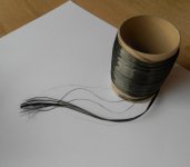
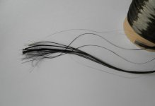
You gave me an idea regarding carbon spring, why not make my own. I got some carbon roving.. each fibre is 7 micron in diameter, so it is just a question of taking the right amount, adding resin and put on a former. Got to give it a try...
Regarding surrounding, I am a bit confused to not sure on with I will use. Hentia talked about a progressive design, it should work nicely on a variety of cone weights sense it it is not tuned to a spec. compliance. He will know.
Regarding surrounding, I am a bit confused to not sure on with I will use. Hentia talked about a progressive design, it should work nicely on a variety of cone weights sense it it is not tuned to a spec. compliance. He will know.
Attachments
- Home
- Loudspeakers
- Multi-Way
- Project Ryu - DIY Field Coil Loudspeaker