Hi,
The low pass filter in this Zaph design is elegant :Zaph|Audio
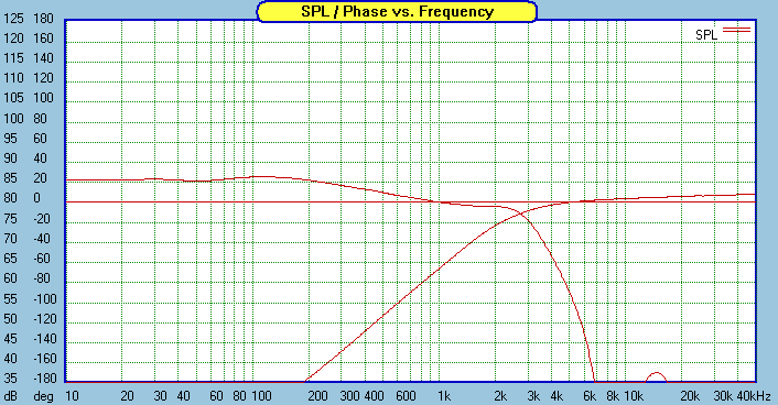
Its a 3rd order (1st order low pass + 2nd order notch) elliptical filter
that combines with the driver and box to deliver 4th order L/R.
Seen this used to good effect in a number of designs.
It struck me that if you are forced to compensate the tweeters impedance
peak in a design it allows a further option I've not seen described in a design.
Instead of simply compensating the tweeters impedance peak use this as
a further way of manipulating the actual high pass function of the tweeter.
E.g. say a tweeter needs compensating and 3rd order electrical to meet
an acoustic (typically L/R) 4th order target. It should be possible to
go 2nd order electrical and overdo the compensation (so it starts to
become a real notch filter) for a similar result.
As in the L18 low pass the eventual slopes will of course be different,
but what being discussed is hitting the acoustic targets around the
crossover point, the further away from that point the more you
can wander from your ideal acoustic function.
rgds, sreten.
A couple of comments.
I looked at the Zaph audio and rather than a 3rd order elliptical I would call it a first order with notch. A fine distinction but he isn't really trying to hit a real elliptical shape and the notch is well enough removed that, looking at the composite curve, you don't really know it is there.
A notch typically puts a quick transition into the phase curve. Phase swings rapidly approaching the notch and comes back in from the other extreme just beyond. This might give useful phase shift and approximate another order, especially if the dip is mild (gentler phase swing) but wouldn't you have to try it on a case by case basis?
I do think I have done a system in the past where I used a mild stop band notch to give a little better initial slope with less stop band phase shift, since the phase comes back. So it can be useful, but it is still hard to generalize about universal use.
I know there is a craze on this site towards the use of Zobels. They can also be set to overcompensate or undercompensate (at which point I wouldn't call them Zobels). For example, more often than not, I use what I call a damped 2nd order woofer network. L in and R and C in series to ground. People would look at it and call it a Zobel but I would not, since no attempt is made to flatten woofer impedance. I just find that 1, 2, or 3ohms at that juncture is often useful for controlling corner Q. We typically use lots of woofer inductor to set the midrange level (box step correction as some insist on calling it) and then adding the appropriate C value to put the corner at the desired frequency results in too high a Q. Hence the shunt R.
Working with optimizers is always enlightening. You iterate around to find the right topology and once you do the optimizer chugs away until the values are right and the necessary shape is achieved. It teaches you that crossover components, in the end, are merely degrees of freedom for adjustment. Put them in the right topology and the appropriate shape can be had.
"Zobel like" circuit sections can be generally useful, especially when you give up the somewhat artifical need to have flat impedance at some point in the circuit.
David S.

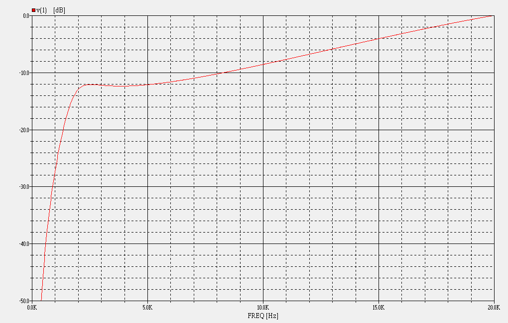
Hi, You can't really see it in the above, but electrically it is an elliptical filter, rgds, sreten.
An externally hosted image should be here but it was not working when we last tested it.
Figure 12 - Low Pass Cauer (Elliptic) Filter Response
Last edited:
I've been using that approach for decades for CD compensation. The first couple octaves above crossover typically need a flat transfer function, since that's where the compression driver is most efficient. Then, at mass rolloff, the slope needs to change to 6dB/octave. So what I do is to set the damping of the core splitter, essentially underdamping it to raise the bottom end of the curve, making it flat up to mass rolloff.


That's exactly what I've done before in the woofer crossover of a 3 way...just by adjusting that resistor value you can shape the corner Q as you say.I know there is a craze on this site towards the use of Zobels. They can also be set to overcompensate or undercompensate (at which point I wouldn't call them Zobels). For example, more often than not, I use what I call a damped 2nd order woofer network. L in and R and C in series to ground. People would look at it and call it a Zobel but I would not, since no attempt is made to flatten woofer impedance. I just find that 1, 2, or 3ohms at that juncture is often useful for controlling corner Q. We typically use lots of woofer inductor to set the midrange level (box step correction as some insist on calling it) and then adding the appropriate C value to put the corner at the desired frequency results in too high a Q. Hence the shunt R.
Particularly useful if you've got the woofer deliberately close to the floor and you need to add some additional downwards slope or "droop" near the upper rolloff point to compensate for overlap between floor gain and baffle gain that you can get with a low woofer and a wide baffle, but without resorting to a 1st order rolloff.
With the right R & C values you have a 1st order with Zobel, with R reduced to zero you have a 2nd order without a zobel, in between those two extremes you have a whole continuum of response shapes, and as you say it is quite interesting to play with the values on a simulator.Working with optimizers is always enlightening. You iterate around to find the right topology and once you do the optimizer chugs away until the values are right and the necessary shape is achieved. It teaches you that crossover components, in the end, are merely degrees of freedom for adjustment. Put them in the right topology and the appropriate shape can be had.
Yep, I agree. Both Zobels and RLC compensators can be set to deliberately over or under compensate the impedance curve to get the desired acoustic response, I tried to make that point in the phase-alignement based method thread but it seemed to get lost in the noise... the example I gave of an "over compensating" RLC notch for a midrange drivers fundamental resonance in a small enclosure is one which I've used myself with great success when trying to use a large driver for midrange without ridiculous amounts of space devoted to the midrange enclosure..."Zobel like" circuit sections can be generally useful, especially when you give up the somewhat artifical need to have flat impedance at some point in the circuit.
Sreten: Thanks for bringing this up. Looks like a very useful circuit
Speaker Dave: Yes optimizers are the way to go for designing. It's beyond my understanding why people still want to do a "trial and error" method for design when there are so many free software and measurement packages available.
DBMandrake: Using a RLC circuit to adjust for midrange drivers in a smaller than normal box is something I've never considered, thanks for the info.
Both Zobels and RLC compensators can be set to deliberately over or under compensate the impedance curve to get the desired acoustic response, I tried to make that point in the phase-alignement based method thread but it seemed to get lost in the noise... the example I gave of an "over compensating" RLC notch for a midrange drivers fundamental resonance in a small enclosure is one which I've used myself with great success when trying to use a large driver for midrange without ridiculous amounts of space devoted to the midrange enclosure...
Its a design school: "First I conjugate the drivers, then I add several dip response corectors, then the baffle step correction for the woofer and finaly a first order network. I like the simplicity of first order networks" !!!
David S.
excuse me for my ignorance but isnt this the same thing as making a 2nd order filter and altering the parallel circuit resistance, to alter the filter q?[ maybe ive missed somethng?/LEFT]
its sounds like adding L to a 2nd order LP in the shunt circuit, and using the dcr of the L to adjust notching. Almost a 1st order with notch centred at the 2nd pole. If so, thats exactly what i did with the xo on my visatons, 1 small mod from the vib130tl schematic to notch out the brebkup even more
its sounds like adding L to a 2nd order LP in the shunt circuit, and using the dcr of the L to adjust notching. Almost a 1st order with notch centred at the 2nd pole. If so, thats exactly what i did with the xo on my visatons, 1 small mod from the vib130tl schematic to notch out the brebkup even more
Last edited:
Do you have a phase curve to go with your figure 12?
Hi,
No I don't. But it will be as bad as you imagine. In Zaphs design the drivers
phase curve is also bad, but it the opposite way, and the two together
give the approximate phase response of a 4th order L/R acoustic function.
rgds, sreten.
I have been playing with the same tweeter, but not with the same luck as John has in this design. My samples roll off so low, I need the full transfer function from the crossover. I have also been totally stymied in managing the 26K breakup. It could be that I am still working with only the tweeter and have not dealt with the 120 degree phase difference my model implies. (using the Zaph midrange)
Mondogenerator, not everyone knows all there is to know about speaker/crossover design and this is DIY and sharing so cut us some slack. It sure beats just having subjective "I know what I heard" discussions on here.Please share with us your knowledge too and we can further our discussion and maybe all learn something.
ok. I gather it is just the same as i imagined, using series R TO CHANGE
the R value, in the R+ jX.... sounds a lot like what many designers have
been doing for years...wheres the discovery?
Hi,
There is nothing new about using the arrangement for a low pass filter
to curb break up modes above the x/o point. But that is not the subject
of the thread, the subject is a similar arrangement in a high pass filter,
and only applies to impedance peak compensated high pass networks.
Only some designers use it for low pass, some still use high order filters,
and I've never seen a documented design that uses it for high pass.
As DBM says, its also applicable to mids if you are compensating their
impedance peaks as well as tweeters. Its not a "discovery", it is
something I've not seen described in any book / article.
Doesn't mean it isn't, but it is obscure and not well known.
rgds, sreten.
Funny, but I just posted an example of using a notch filter to control phase in another thread, showing with and without.A notch typically puts a quick transition into the phase curve.
apologies. It wasnt my intention to appear critical, i was trying to get my head round what the circuit looked like in my head. Im by no means an expert, but i have simmed such thing on occasion using boxsim, but im not sure ive really considered it thoroughly. It seems a little like all pass stages added to a bring phase back, in that the advantage comes with higher complexity, and all that entails.interesting subject though, and i hadnt seriously thought of this approach
Instead of simply compensating the tweeters impedance peak use this as a further way of manipulating the actual high pass function of the tweeter.
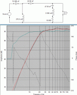
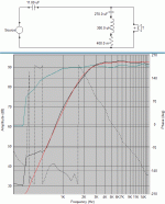
Attachments
Hi Sreten,
Thanks for starting this thread. It is indeed an interesting approach to overcoming the tweeters impedance peak problem at its resonance. It occurred to me that with such a topology, you may also be able to implement the so called “Neville Thiele Method” Xover as described in this link, NTM Crossovers
where a notch is deliberately inserted into the HP filter response, to compliment that in the LP response.
With your observations in mind, it seems that the same circuit topology might be used to implement either a LR or NTM type Xover simply by changing the notch depths.
Regards
Peter
- Status
- This old topic is closed. If you want to reopen this topic, contact a moderator using the "Report Post" button.
- Home
- Loudspeakers
- Multi-Way
- Deliberately incorrectly doing tweeter impedance compensation

