It's very hard to tune a hole! That's how many vented enclosures were made in the past, before we knew what we know today, and they sounded pretty terrible. You need a long enough port so that end effects don't swamp out what you're trying to accomplish. The port works because of the mass of the air within it. One way to get more mass is to use a passive radiator, but that comes with its own problems. Small speakers are often problematic because you don't have room in the box for a port of sensible dimensions. In that case you typically have to stop worrying about port noise and reduce the diameter. I use a set of KEF "Q" speakers for the TV and they have flared ports a little over an inch in diameter. They have surprisingly good LF response, but you'll never feel it in the chest like a larger speaker. IMO, with a small bookshelf speaker you won't be moving enough air to worry much about port noise.
I use a set of KEF "Q" speakers for the TV and they have flared ports a little over an inch in diameter. They have surprisingly good LF response, but you'll never feel it in the chest like a larger speaker. IMO, with a small bookshelf speaker you won't be moving enough air to worry much about port noise.
I like the way you think and I also like flared ports. The one I used is from jentzen and I just looked and there is a smaller version. Will do some testing whit lower tuning and see whats happens.
As far as I know the surface of port should be equal or at least half of surface of driver. This is to avoid any noise created by port itself.
There's more than Sd to take into consideration. Sd by itself doesn't paint a large enough picture to make any determinations about necessary port cross section.
I know that because of limitations of design this is rearly used, but I think I can use that size of a port and live with this design.
The current tuning results in a bass response that people point and laugh and joke about as a typical max-SPL one-note-wonder cheap car stereo sub. I wouldn't be able to live with that at all....
[emphasis added to the following quote...]
The reason for high tuning frequency is as said before to be able to get out more from this driver in relation to cone displacment.
A proper tuning would provide useful extension to down around 50hz. IMO, that would be more.
The idea is to have port tuned at Fs of the driver. The simulation didn't look that problematic.
I can't get my head wrapped around the idea of a 10dB spike in response being less problematic than a 7dB dip

Thanks, will try diffrent port and see or rather hear what happens
I'm excited to hear your impression of the change!
Regards,
Eric
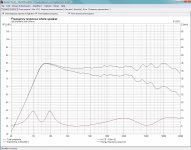
Here is picture of simulation, and from this I was thinking that a few dB peak as seen here 3 dB would be nice and add to that a perfect impedance curve I just had to try it
I have already tryed a longer port and it is much better, will post mesurment when I will done it.
I have already tryed a longer port and it is much better, will post mesurment when I will done it.
Attachments
This one (vented) doesnt't sound good.
What do you think about this driver, seales box for q 0,9 the calculations says 2,4 liters and fs of system 125 Hz. Would this be way too high?
Some time ago I did a lot of band pass push pull sub with center frequency around 80 Hz and always loved sound.
What do you think about this driver, seales box for q 0,9 the calculations says 2,4 liters and fs of system 125 Hz. Would this be way too high?
Some time ago I did a lot of band pass push pull sub with center frequency around 80 Hz and always loved sound.
In theory the port should be as big as loudspeaker and since there is enought space I decided to use this one. I don't think that smaller diameter would make any differenc or would it?
Wouldn't it be only shorter for the same tuning?
I think your "theory" is a bit confused.
Vent cross section area does matter, but only insofar as vent velocity is kept under 17m/s
I'm no expert on the mater, but Loudspeaker design cookbook, which I think is a good reference says that port should be "nearly equal to the driver area as possible"I think your "theory" is a bit confused.
Vent cross section area does matter, but only insofar as vent velocity is kept under 17m/s
Look at your simulation, compare it to my simulations, there is a major difference. Look at your response measurements, they more closely mirror my simulations than yours. I'm not sure how you are simulating, or what you are doing exactly, but there is obviously some error going on there. The measured response confirms the nasty peak in response predicted by hornresp when I estimated your port dimensions.
If the Loudspeaker Design Cookbook does actually say that, then it is in error for the vast majority of driver/box combinations that are rational. More importantly, even if you do want to have that enormous port diameter, it needs to be a LOT longer to achieve an appropriate tuning. I don't know how in-depth the book goes in regards to vented alignments (never read it), but I'd have to imagine that if the book discusses ported enclosures, it would cover appropriate tuning concepts. A port with a cross section equalling the driver Sd, is more akin to a transmission line build. A different animal for sure.
Regards,
Eric
That's so wrong. Port dimensions can be derived from a formula and experience that confirms it as so many designers know. (Not many people know it for sure.)I'm no expert on the mater, but Loudspeaker design cookbook, which I think is a good reference says that port should be "nearly equal to the driver area as possible"
Go believe in everything people tell you...
That's such a good point and correction Eric.Look at your simulation, compare it to my simulations, there is a major difference. Look at your response measurements, they more closely mirror my simulations than yours. I'm not sure how you are simulating, or what you are doing exactly, but there is obviously some error going on there. The measured response confirms the nasty peak in response predicted by hornresp when I estimated your port dimensions.
If the Loudspeaker Design Cookbook does actually say that, then it is in error for the vast majority of driver/box combinations that are rational. More importantly, even if you do want to have that enormous port diameter, it needs to be a LOT longer to achieve an appropriate tuning. I don't know how in-depth the book goes in regards to vented alignments (never read it), but I'd have to imagine that if the book discusses ported enclosures, it would cover appropriate tuning concepts. A port with a cross section equalling the driver Sd, is more akin to a transmission line build. A different animal for sure.
Regards,
Eric
Look at your simulation, compare it to my simulations, there is a major difference. Look at your response measurements, they more closely mirror my simulations than yours. I'm not sure how you are simulating, or what you are doing exactly, but there is obviously some error going on there. The measured response confirms the nasty peak in response predicted by hornresp when I estimated your port dimensions.
You are right, will try to contact author of the program so he can have a look if I made some error whit the project. Tuning of the box is at 75 Hz.
If the Loudspeaker Design Cookbook does actually say that, then it is in error for the vast majority of driver/box combinations that are rational.
Yes it says this I think somewhere around page 76 I had a look, but as I said it isn't practical in theory as you had writen because of large dimensiones of port.
I'm not super up-n-up on the whole workings of room diffraction and such, however, considering the original 147hz dip issue, this corresponds to about a 90 inch round trip cancellation if I understand correctly. From your test position, are there many boundaries ~45" from your microphone? Or a number of boundaries that sort of average out to about a 45" distance?
I think your calcualtion are spot on the hight of room is around 90"
Do you have any formula for calculating minimum port surface or any softwere so I don't neet to look all over te internet for it?
I would like to use flared port Aand I can get it from jantzen. The smalesta available is diameter 35 mm, would that be enought?
the hight of room is around 90"Do you have any formula for calculating minimum port surface or any softwere so I don't neet to look all over te internet for it?
I would like to use flared port Aand I can get it from jantzen. The smalesta available is diameter 35 mm, would that be enought?
WinISD Pro Alpha (free) is a box simulator that can calculate and graph port air velocity versus frequency for any particular design at any power level.
http://www.linearteam.dk/default.aspx?pageid=winisdpro
After entering the driver parameters and choosing the box size and port frequency to get the bass alignment you want you would enter a power level that corresponds with maximum expected output SPL and it will graph port air velocity. (To help determine the power level you can use the maximum SPL graph which shows maximum possible output based on excursion and power handling figures)
Keep the peak velocity near the port tuning below 17m/s for a non-flared port and you should be fine. If its above 17m/s increase the port diameter until it isn't and the app will recalculate the port length to keep the resonant frequency the same. Simple.
Well designed flared ports can go a bit above 17m/s but most software can't calculate or simulate them for you as it requires a full 3d model of the port and a complex fluid dynamics simulation - way in advance of what most (all?) box simulators do.
And yes, your notch at 147Hz will definitely be room modes and/or boundary cancellation. Nothing to worry about as there isn't anything you could do wrong in the speaker design to get an actual notch in the response like that. Doing a near field measurement will allow you to measure up to 200Hz or so without room effects, and you would see the notch disappear in that case.
Last edited:
I like hornresp personally, I used to use winISD pro exclusively because it was all I knew. Even after learning of hornresp, I continued using winISD for awhile because I was wading through the steeper learning curve of hornresp, however, I think it's well worth the effort to learn how to use the program. It can simulate the effects of far more complicated enclosures, far more accurately than winISD. A flared port simulation in hornresp will actually show the effects of a flared port, on response, excursion, and particle velocity. winISD can't do that.
Regards,
Eric
Regards,
Eric
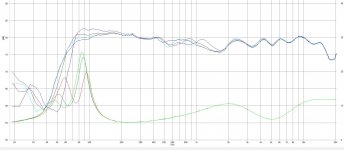
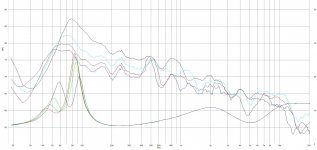
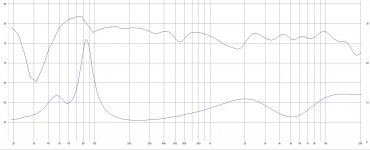
Here are mesurments with frequency tuning at 55, 60, 65 and 75 Hz. My favorite is 60 Hz so thats the one on last picture, but the plot is combined mesurment of driver and port. On a first picture are mesurments made on axis of driver at closer range 0,36 meter and the resolution is 1/6 octave. For the last picture all is the same except I combined plot with port mesurment. On the second picture I mesured only port using same resolution, but close range around 10 cm away for the same frequency tuning as above.
Any idea what could be the source of peak at around 500 Hz?
Any idea what could be the source of peak at around 500 Hz?
Attachments
Any idea what could be the source of peak at around 500 Hz?
Quarter wave box resonance would be my guess. I honestly don't even know if that is the correct terminology to describe it.
Last edited:
- Status
- This old topic is closed. If you want to reopen this topic, contact a moderator using the "Report Post" button.
- Home
- Loudspeakers
- Multi-Way
- Problem in response